Watching TV is one of my favorite activities, but I noticed it’s become too easy for kids (and adults) to fall into the endless loop of short, addictive YouTube videos instead of enjoying a thoughtful episode of a TV show or diving into an adventure movie. I got tired of seeing my kids glued to the screen watching yet another YouTuber attempt a ridiculous “Fast-Food Challenge.”
So I decided to make good content more accessible - and fun to play. The result: watching content on the TV by scanning physical Movie Cards with NFC. I call it CardFlix.
CardFlix in action
This project was a great opportunity to involve my kids in electronics, showing them how to make something truly useful by building it together.
The scanner runs on ESPHome - a framework that makes creating custom smart devices surprisingly simple, and connects to my Home Assistant smart home setup. With my kids’ help, we created over 50 cards covering all their favorite shows and movies, and the collection keeps growing. It was such a hit that I built a second scanner for another room in our house. To make the scanner blend in, I designed and 3D-printed a small enclosure that matches the décor of the room while keeping the scanner kid-friendly and accessible.
Creating the initial version of this scanner was a fun weekend project. I was able to show my kids the process of bringing an idea to life, in addition to me gaining more confidence creating ESPHome projects, which became more useful for other projects that I’ll share soon.
Building the electronics
The circuit is straightforward: connecting an NFC reader module (PN532) to a microcontroller (ESP8266WeMos D1 mini).
Circuit diagram showing the PN532 NFC reader connected to the microcontroller
To connect a microcontroller, like the Wemos D1 Mini, to an NFC reader (or other peripherals such as sensors, displays etc.) there are 2 common methods: I²C or SPI. SPI can handle higher throughput than I²C and is generally faster, which is good if we connect an LCD display and need to move a lot of pixels quickly for it, but it’s not particularly useful for a simple tag scanner. I chose I²C because it’s simpler to hook up, it needs only 2 wires in compare to 4 wires we need to support SPI connection.
One critical step to note here: set the PN532’s mode correctly. The board has tiny DIP switches to toggle between I²C and SPI. Make sure these match your chosen mode - otherwise you’ll be staring at a non-responsive scanner and wondering why nothing works. Let’s just say I learned that lesson the hard way…
Flipping the PN532 mode from SPI to I²C
Once the correct mode is set, I wired the SDA and SCL pins from the PN532 to the Wemos D1 mini. You can map I²C lines to almost any pins on the microcontroller; I chose D8 (for SDA) and D7 (for SCL). These need to match what we’ll later declare in the ESPHome config:
After confirming the wiring, I soldered everything together. A pair of helping hands was invaluable here - keeping the boards aligned so I could stack them neatly and compactly. That’s important, since they need to fit snugly inside the enclosure, as we’ll see later.
Soldered electronics stack help by the helping hands
BTW, the reason I picked the Wemos D1 mini as the microcontroller for this project is because of its size. I knew I would need to eventually mount the device near the TV, so having a small form-factor is a useful feature. ESPHome, which we’ll talk about next, supports several other microcontroller types in different shapes and with varied capabilities. Even this baby-chip is supported.
Smart Home Integration
With the hardware stacked and soldered, it was ready for the fun part - bringing it to life through ESPHome and tying it into Home Assistant, where we’ll write an automation to make the scanner react to different cards.
If you’re not already using Home Assistant, it’s an open-source smart-home platform that brings all your devices together - TVs, phones, sensors, air conditioners, and much more. You can easily run it on a Raspberry Pi, an old PC, or a virtual machine, so even if this is your first smart-home experiment, you can still install it just for this project
ESPHome Config Basics
The scanner runs on ESPHome, which makes connecting hardware like the PN532 reader almost trivial. Instead of writing firmware, you just declare the pins and components in YAML, and ESPHome takes care of the rest.
esphome:name:cardflix_scannerplatform:ESP8266board:d1_minii2c:sda:D8# The pins we connected earlierscl:D7scan:true# optional, helps confirm wiringpn532_i2c:id:nfc_reader
“Installing” this config on our microcontroller involves connecting it to the computer and using 2 web tools that do everything. The first tool, ESPHome Builder (a Home Assistant Add-on), parses the yaml config and generates the firmware based on the info on that config. The second tool, ESPHome Web, connects to your device via USB cable and flashes the firmware onto it. There are plenty of good instructions for the process, such as this youtube video or the official ESPHome instructions.
From ESPHome → Home Assistant
Once the firmware is loaded onto the Wemos D1 mini, Home Assistant automatically detects the device and prompts you to add it as an integration.
Home Assistant integration setup screen
From there, the scanner can report any NFC tags it detects. Home Assistant has an Event Listening feature under Developer Tools, a quick scan of any card, while listening to “tag_scanned” events, will show some useful data for the card and the tag scanner. tag_id is the card’s unique ID and device_id is the tag scanner’s unique ID.
Event Listener showing tag_scanned event data
We could also write data onto the cards, but we won’t do that here. There’s no need to complicate the process of onboarding new movie cards, since each card already has a permanent unique identifier (the tag_id we see above). We’ll design an automation that maps each card’s Tag ID to the content we need to play.
Writing the Automation
There are a few ways to set up the automation. I liked the structure Xavier at Simply Explained shared, it keeps the mapping of Tag IDs to content easy to read and update.
I made a few changes of my own:
Support for multiple scanners (so different rooms can have their own devices).
Some tweaks to handle different types of content (Plex, Netflix, etc.).
Here’s how it works.
1. The automation’s trigger - scanning a card.
The trigger is a tag_scanned event, the same one we saw earlier when testing the scanner using the Developer Tools. The automation will be triggered when such an event is fired.
The Automation's trigger configuration for tag_scanned events
2. Defining the variables we need.
These are the variables the automation uses:
SCANNER_MAPPING - A simple mapping between Scanner IDs to the TV entity they should operate on. This will ensure that the scanner in the bedroom will start any playback on the Bedroom TV and not other TVs. We can get the Scanner ID using the Event Listener tool we saw earlier.
TARGET_TV - This variable resolves to the TV entity the automation needs to target, based on the Scanner ID that was provided by the tag_scanned event (trigger.event.data.device_id = The Scanner ID). This also defines the default TV in case the scanner is not mapped to any specific TV (In this case, the default is Living Room TV).
CARD_MAPPING - Maps each card’s Tag ID to the content it should play.
The automation's variables, we'll mostly update CARD_MAPPING with Tag IDs and content IDs
Each card mapping includes the Tag ID, a name (just for readability) and the Content ID. The automation supports a few content types, for several streaming services and Plex. We’ll see below how we deep link to open the content.
3. Turning on the TV, if needed
The TARGET_TV variable holds the TV we’re targeting, we’ll check its status and turn it on if needed.
TV power control logic in the automation
4. Start the requested content using the content mapping defined in CARD_MAPPING
Each streaming service has its own Deep Link format. For each content we’ll check the streaming service it’s using, retrieve the correct deep link format and use it with the content’s ID to start the playback.
In the example below, looking up the Tag ID in CARD_MAPPING provided a “netflix_id”, which we used as part of the Netflix Deep Link URL, like this:
The URL is sent to my Apple TV as a “Play Media” request.
This URL works on an Apple TV, which is connected to my TV. It’s possible other media devices, such as Smart TVs, would have different requirements to deep link to a specific content.
The flow of playing a Netflix content in the automation
These are the main logic of the automation, the full yaml code is available here.
Deep Linking to Content
Deep links are URLs that open a specific content on a specific streaming service. Not all of them are properly documented and some of them might not work on every streaming device (e.g. Apple TV, Smart TVs, Roku device). These are the Deep Link URLs that I found to be working on an Apple TV:
plex://play/?metadataKey=%2Flibrary%2Fmetadata%2F<Content ID>&server=<Plex server ID>
Plex Playlist
plex://play/?metadataKey=%2Fplaylists%2F<Content ID>&server=<Plex server ID>
The Content ID can be retrieved by opening the content on your browser and checking the URL.
Tip: Using a Plex playlist is a great way to watch random episodes of some TV Show(s), perfect for shows the kids have already watched a hundred times. Instructions on how to do that.
And here’s the automation in action:
Demo video testing the automation
Creating the Content Cards
The electronics and automations are only half the story — the real magic (and the part my kids loved most) was creating the movie cards themselves.
Each card is laminated with the TV/Movie’s artwork. The laminate not only makes the cards sturdy enough for repeated use, but also gives them that satisfying “real card” feel
We used fanart.tv as our main source for high-quality TV and movie artwork. It has a huge collection of posters, logos, and backgrounds that work perfectly for this kind of project. Once we picked the right art, we copied it into a Google Doc and resized it to the dimensions of a credit card (Tip: resize to Width 2.12 inch, Height: 3.36 inch, Ratio: 1.583333). We put a few posters on a single page and printed it.
Arranging the movie posters for printing
The printed poster we put on top of the card, slipped into a Laminating Pouch and from there straight to the laminating machine. The one I got is cheap (under $20) and it served us well in several projects, definitely nice to have around the house.
My daughter Emma is showing how we lamindate a movie card
Onboarding a New Card
Once the physical card is ready, the final step is onboarding it into Home Assistant. To make things easier, I’ve added to the automation a fallback in case we scan a card that’s not assigned to any content, which prints the card’s Tag ID to Home Assistant’s Logbook.
The "Else" clause of the automation, printing the card's Tag ID to the Logbook
This is how the Logbook entry looks like:
Home Assistant's Logbook entry detailing the Tag ID of a new card to onboard
Then all we need is to add a new entry in the CARD_MAPPING variable inside our automation:
By streamlining this process we made it very easy to grow the collection. Every time we want to add a few new TV Shows or Movies - I would search the content IDs in the streaming services, while my kids handle the card laminating step and we would meet at the end by scanning the cards and adding the new mapping for each new card. We don’t need to leave the house for a fun family activity.
3D Printing the Enclosure..and more
With the electronics and cards ready, the last step was giving the scanner a proper home. I wanted it to be accessible for the kids while being subtle enough to blend into the room’s décor.
Instead of designing something from scratch, I started with an existing enclosure I found online and personalized it with a simple logo that ChatGPT helped create. The result was a clean, kid-friendly enclosure with a custom logo that makes it feel like a finished product.
Desgining a 3D printed enclosure with a custom CardFlix logo on the BambuLab Slicer
I printed the design on my Bambu Lab printer, using standard PLA. The compact stack of the electronics fit snugly inside, with just enough room for the wires and solder joints.
3D printed enclosure assembly and final mounted scanner
To keep the cards organized and accessible I created 2 boxes - one to hold a large group of cards, another for holding a small group of “most favorite” cards next to the reader.
Card storage boxes - large collection box and slim favorites box
And in case you wonder, there are 4 Bluey cards in those boxes…
With the hardware soldered, the enclosure printed, the Movie Cards laminated, and the automation wired into Home Assistant - it was time for the payoff.
Complete CardFlix setup showing scanner and card collection
Here’s a short demo of the scanner in action:
Final demo video - this is how we usually play content, using the "most favorites" box.
No menus, no remotes, no digging through apps. Just the card, the scanner, and the content.
It’s been a huge success in our house - my kids love the ritual of picking a card and watching it come to life, and it gives them a healthier, more intentional way to choose what to watch.
Closing Thoughts
This project started as a way to combine electronics tinkering with something useful for the family, and it turned into one of our favorite weekend builds. Between the hands-on soldering, designing the cards, and the 3D-printed enclosure, everyone got a part to play - and the end result is something truly useful.
If you’d like to build your own, all the relevant links to get you through that are below. And if you do make one - I’d love to hear about it!
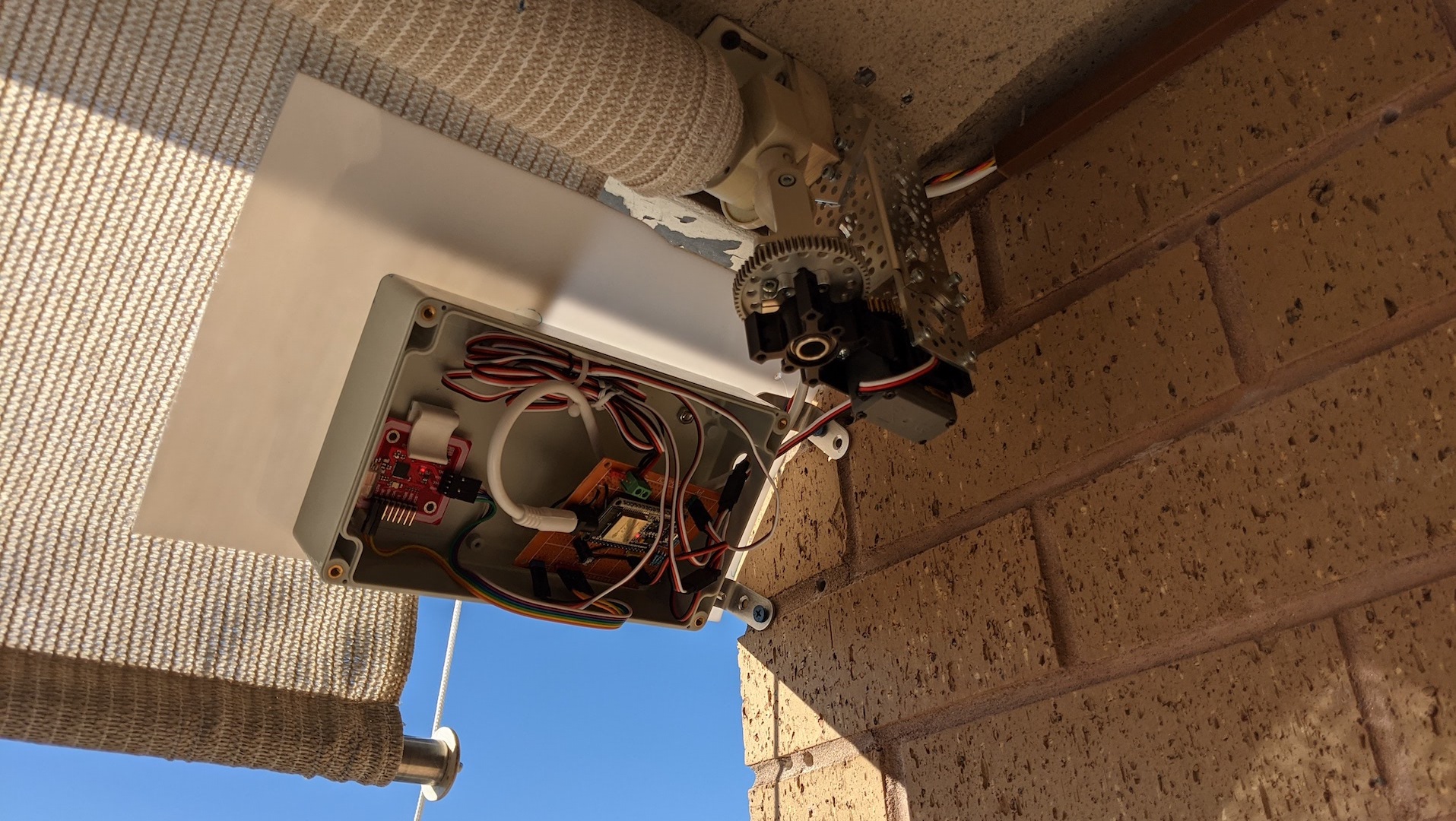
These past few months I spent mostly at home, as everyone else, and decided to take on a project to improve my time there. With three kids at our cozy apartment, it’s no wonder I loved spending a lot of time on our balcony. While I like the breeze and the view, I hated lowering and raising the sun shade. It’s a heavy shade, so it took more effort and time to operate than a regular bedroom window shade/blinds. I challenged myself to automate this shade by any means necessary!
I found a strong motor, designed a circuit and programmed a microcontroller to run the show. I mounted a switch box with up/down buttons and used NFC to support “shade presets”. Finally, I got everything connected to the internet and respond to voice commands from Google Assistant. The result:
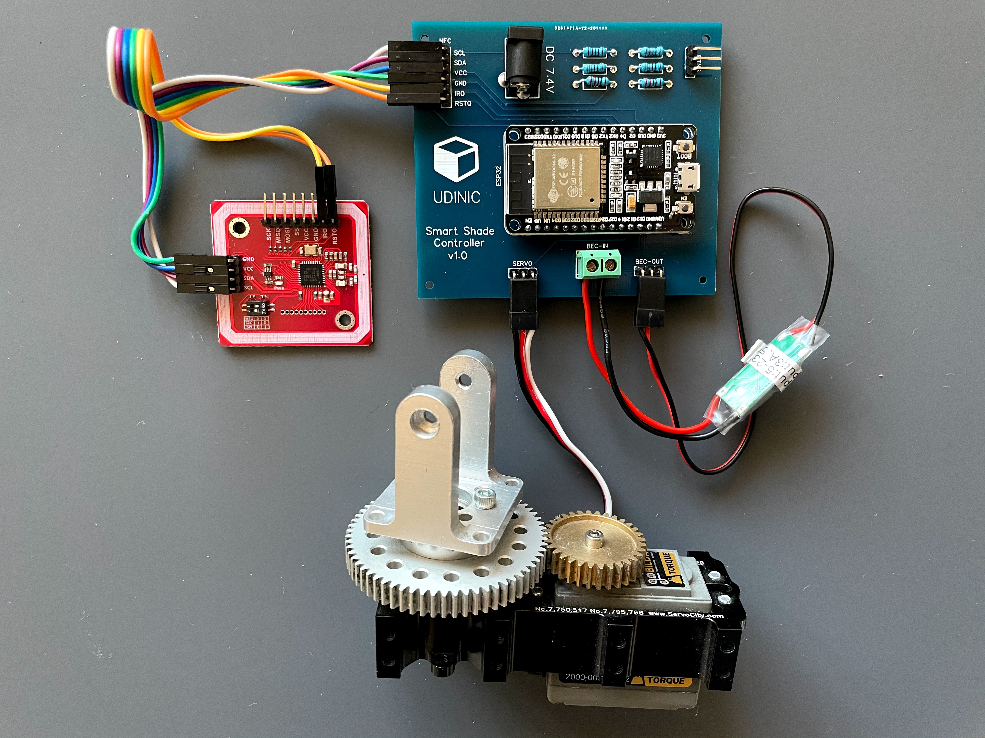
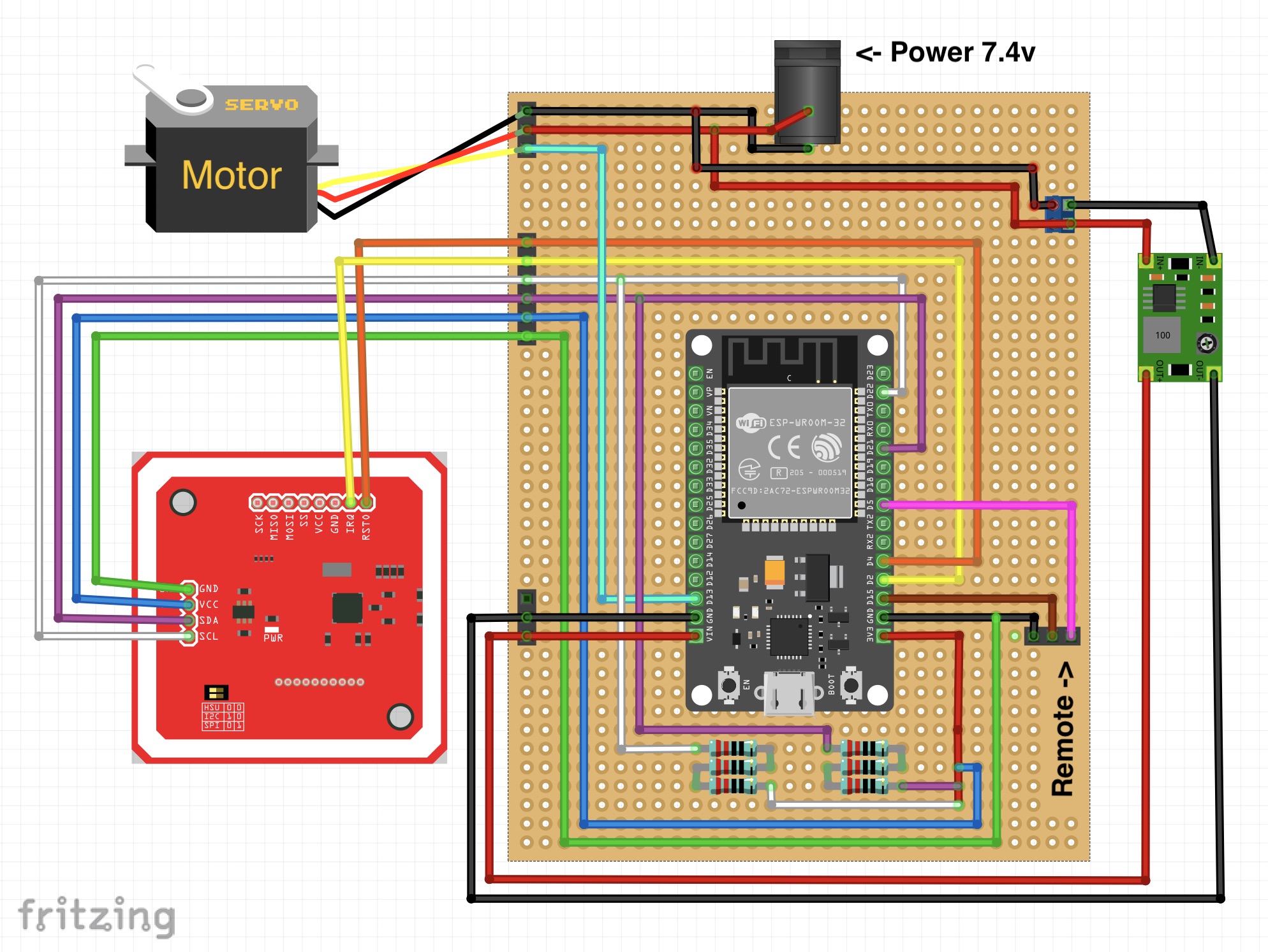
The complete smart shade controller circuit
Demo of the smart shade controller
That was quite a journey.
I dived into the world of Arduino, where I learned how to design and program circuits. I also gained a better grasp on mechanical engineering concepts and got some experience applying them in real life. At the end, I had a polished Shade Controller that works reliably and safe for everyone to use, including my kids.
In this post I wanted to share my experience building a smart shade controller from scratch. Here’s an overview of the steps I’ll cover:
Finding a suitable motor and figuring out how to attach it to the shade.
Building the circuit and testing it in my balcony.
Taking automation to the next level by using NFC (Near-Field Communication).
Improving the appearance of the shade controller.
Supporting voice commands using Google Assistant.
Tips and lessons learned.
I think the creation process was a cool experience that’s worth the read on it’s own, but I also hope that some of my methods, research and learnings will help others undertake similar projects.
Setting up the Motor
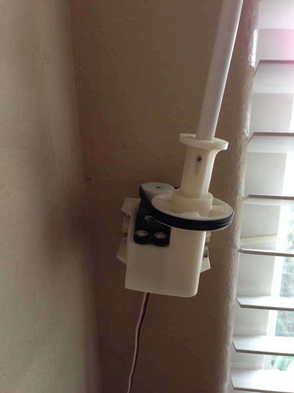
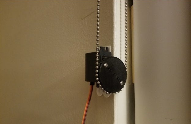
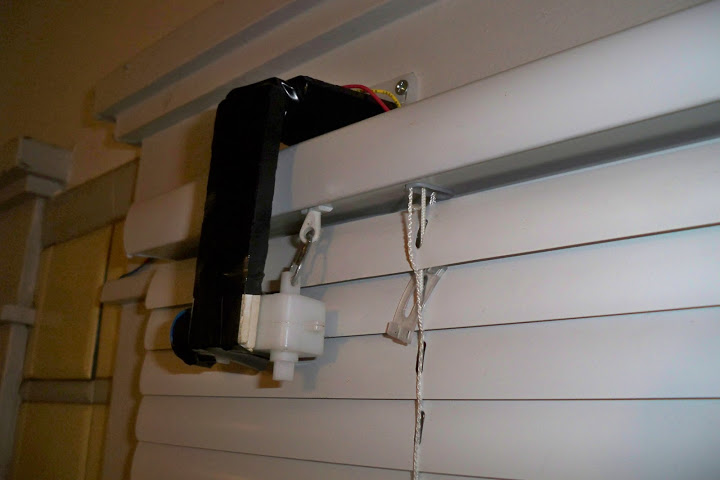
Building a custom smart shade/blinds is a pretty common project, but as I researched this subject I didn’t find a solution that fits the type of shade I have. In most of these examples, the motor was moving the blinds by pulling a chain or rotating a small twist shaft.
Examples for other smart shade projects. Click on each image to see the relevant project.
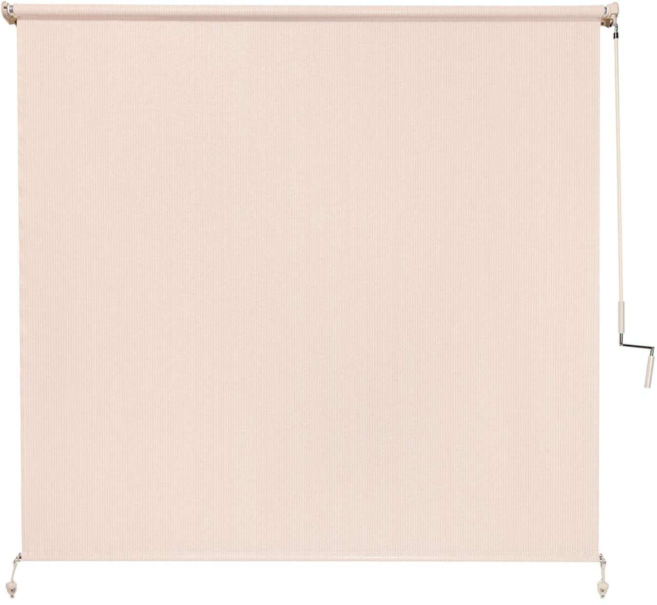
The shade I installed in my balcony is much bigger and heavier than most of these shades. It’s 8 feet wide, weighs 8 pounds and uses a crank and a wand to operate.
The shade I have on my balcony
To start, I need to find a strong motor that can actually move this shade. There are ways to measure the force needed to move the shade (like using a luggage scale), but I ended up consulting my mechanical engineer brother, who helped me pick a motor that should be strong enough for the job. I found a Servo motor that’s strong by itself, but it also comes inside a gearbox that increases its torque (and I could use all the torque I can get!). The gearbox has 2 gears in a 2:1 ratio, which produces half the speed of the original servo motor, but with twice the torque. To close or open the shade we need to rotate the crank 60 times, so with the 31 RPM the motor can do - it’ll take about 2 minutes. That’s reasonable enough.
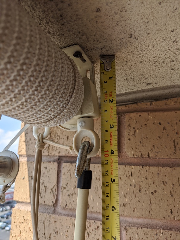
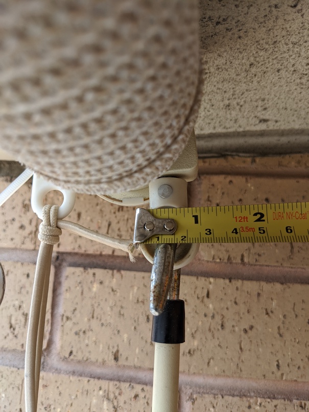
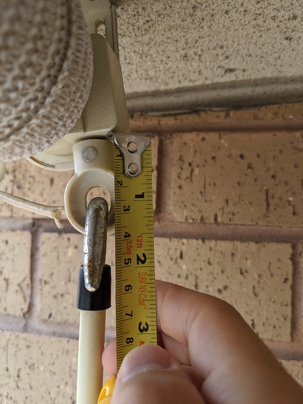
Now that I have a motor, I needed to find a way to mount it on the roller and get it to rotate the crank. I took measurements and started researching…
Taking measurements
Connecting the motor to the crank and rotating it was also not trivial. I took some measurements, but I don’t have a 3D printer so I can’t just print a perfect adapter. Luckily, after some online searching I found a bracket that fits perfectly! To celebrate, I did an initial test to verify the motor can actually move the shade in both directions:
Testing the motor
A successful mount of the motor needs to produce a smooth crank rotation while the motor spins, any misalignment between the rotation planes of the motor and the crank could cause friction that damages the shade’s mechanism or the motor. Getting this alignment right was found to be quite challenging.
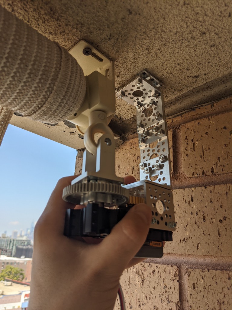
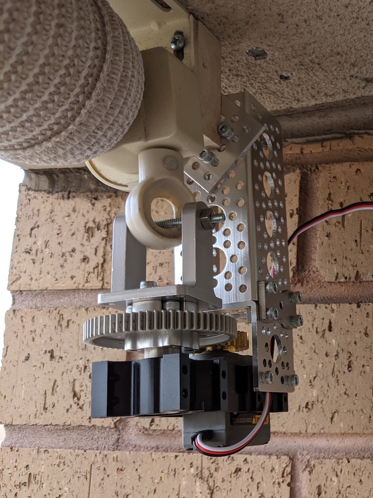
Since I don’t have a 3D printer, I had to improvise a setup with existing structural components. I found ServoCity, a well-organized website that sells parts for projects like this. On the site, I found and ordered a bunch of different structural components that might help me. I used various metal plates and brackets to mount the motor in different ways, testing the crank’s rotation and making adjustments. After some trial and error, and a bunch of new holes in my wall, I eventually found an arrangement that worked.
Mounting the motor. First attempt on the left, final position on the right.
Cool, now that I have the motor in place - I need to build the circuit that controls it.
Building the Shade Controller Circuit
My initial requirement for the shade controller was simple: have 2 buttons that can spin the motor in both directions. That was a great excuse to start tinkering with Arduino, something I wanted to do for a while. So I dived right in.
Simple circuit to spin the motor in both directions.
The 2 buttons are connected to the Arduino through the breadboard, each one is connected to a different pin on the Arduino board. The code constantly reads the value of these pins to detect when a button was pressed. By default, each pin returns the value HIGH but during the time a button is pressed the pin’s value will be LOW. The code ignores long presses and acts only when a button changes state, which is why we compare the current pin’s value to the previous one.
#include<Servo.h>// Pin definitions#define PIN_SERVO (13)
#define PIN_UP_BTN (5)
#define PIN_DOWN_BTN (15)
ServomyServo;// ...voidsetup(){// Setting up the button with the pins they're wired topinMode(PIN_UP_BTN,INPUT_PULLUP);pinMode(PIN_DOWN_BTN,INPUT_PULLUP);}// Main function that loops as long as the controller is powered onvoidloop(){// Reading the value in the pins connected to the buttons.// The default read will be HIGH, while pressing a button it's changed to LOWbtnUpCurr=digitalRead(PIN_UP_BTN);btnDownCurr=digitalRead(PIN_DOWN_BTN);// The UP button is pressed if(btnUpCurr==LOW&&btnUpPrev==HIGH){// If the motor is already spinning - stop itif(raisingShade||loweringShade){stopShade();}else{raiseShade();}}// The DOWN button is pressed if(btnDownCurr==LOW&&btnDownPrev==HIGH){if(raisingShade||loweringShade){stopShade();}else{lowerShade();}}btnUpPrev=btnUpCurr;btnDownPrev=btnDownCurr;}
The Servo motor is also connected to one of the Arduino’s pins, using the yellow/white wire. Controlling the motor is done using an API that’s part of a Servo library.
voidlowerShade(){myServo.attach(PIN_SERVO);// Value smaller than 1500 will spin the motor counter-clockwisemyServo.writeMicroseconds(850);loweringShade=true;raisingShade=false;}voidraiseShade(){myServo.attach(PIN_SERVO);// Value larger than 1500 will spin the motor clockwisemyServo.writeMicroseconds(2100);raisingShade=true;loweringShade=false;}voidstopShade(){raisingShade=false;loweringShade=false;myServo.detach();}
Internally, the Servo library is controlling the motor by sending it signals in “different formats”, which contain the position and direction the motor should be spinning. For more on that, check out how Pulse-Width Modulation works.
After getting this simple circuit to work, I decided to replace the Arduino board with a smaller microcontroller - the ESP32.
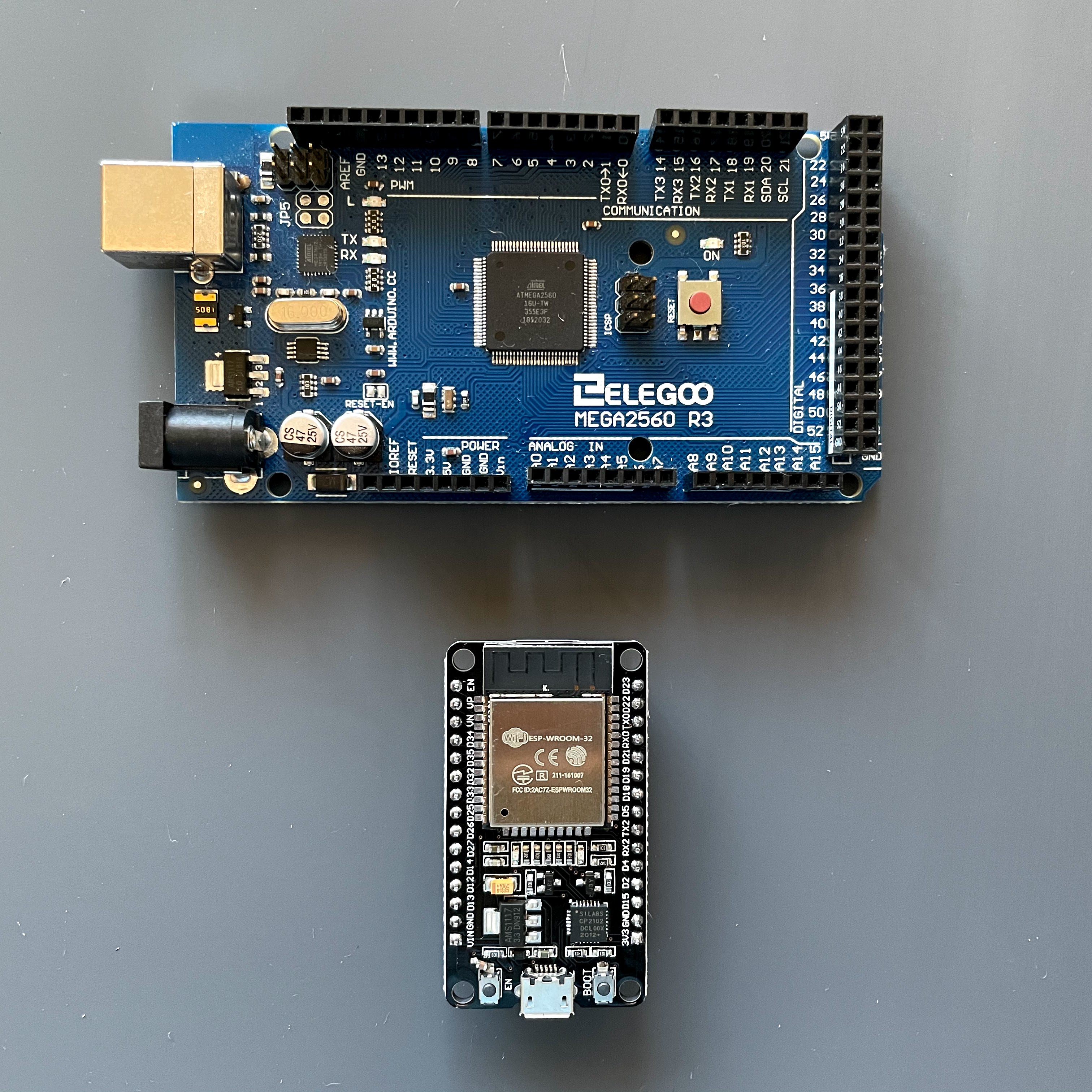
Arduino vs. ESP32
Arduino is an open source hardware and software for electronics hobbyists. The board I have, the MEGA 2560, is Arduino-compatible. It was not manufactured by the Arduino company but it did use the same open source Arduino hardware design. This means I can use the Arduino IDE to program my board and utilize the great variety of Arduino libraries to integrate with external sensors and peripherals. The ESP32 hardware was not built by the same Arduino specification, but its software bridges the gap between the 2 hardware designs. This means we can program the ESP32 almost exactly the same as an Arduino board or an Arduino-compatible board, even though they are very different.
Why choose ESP32 over an Arduino board? Well, Arduino is great for beginners because it’s simpler to use and easier to get started. However, the ESP32 is more powerful, smaller, cheaper and supports Bluetooth and WiFI, which the Arduino doesn’t. To make it easier to work with, the ESP32 chip comes integrated in a small dev-board that has features like micro-USB connector and voltage regulator, as well as easier access to all its pins (like an Arduino board has).
I wanted my circuit to have a small footprint and I also had plans for using the WiFI feature, so I bought a couple of ESP32 dev boards. I migrated my code to be compatible with ESP32, which basically was just updating to an ESP32-flavored Servo library.
Using an ESP32 to control the motor.
I also updated the circuit to power the motor and the ESP32 from a single battery, but more on that later.
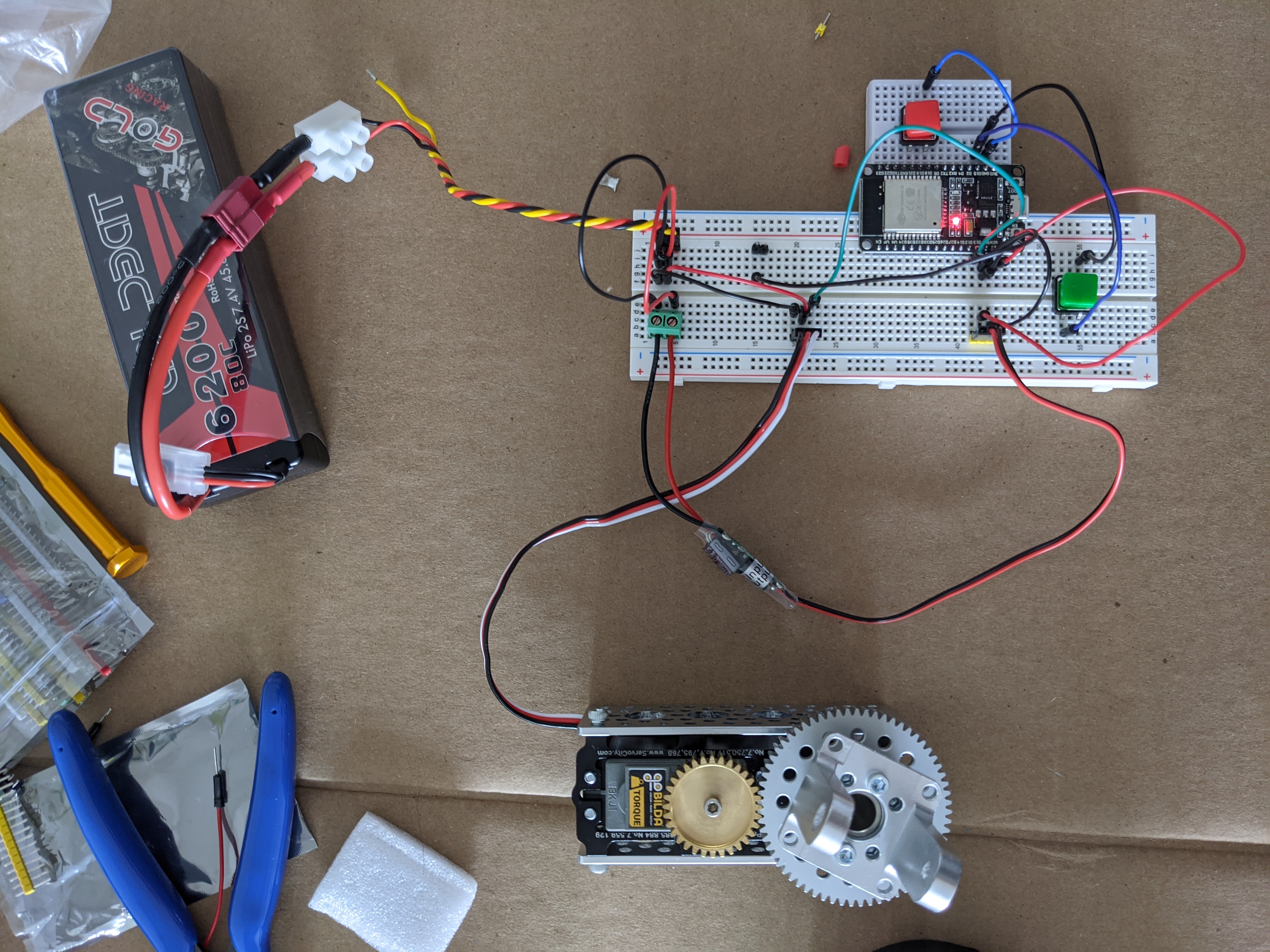
Now that I have the basic circuit for my shade controller, I can start testing it at my balcony. So far I tested my circuit on a breadboard, but I want something more reliable for my first prototype. I took out my soldering iron and built the circuit on a perfboard.
Soldering the components for the shade controller prototype.
To test it, I hung the shade controller circuit next to the motor with zip-ties and connected the motor to it. The battery is also there at the back, inside a ziplock bag. Nothing too fancy for a first prototype.
The first shade controller prototype.
I also added a 2-button remote, for a better accessibility when trying to operate the shade from my balcony chair.
Now that everything is in place, I can test the first prototype:
Testing the prototype
The First Prototype
It was a real treat using my prototype for a couple of weeks! The shade controller worked well - it was responsive and the motor raised that shade like a champ! There was only one problem I found, but before diving into that - let’s first get to know the prototype a little better.
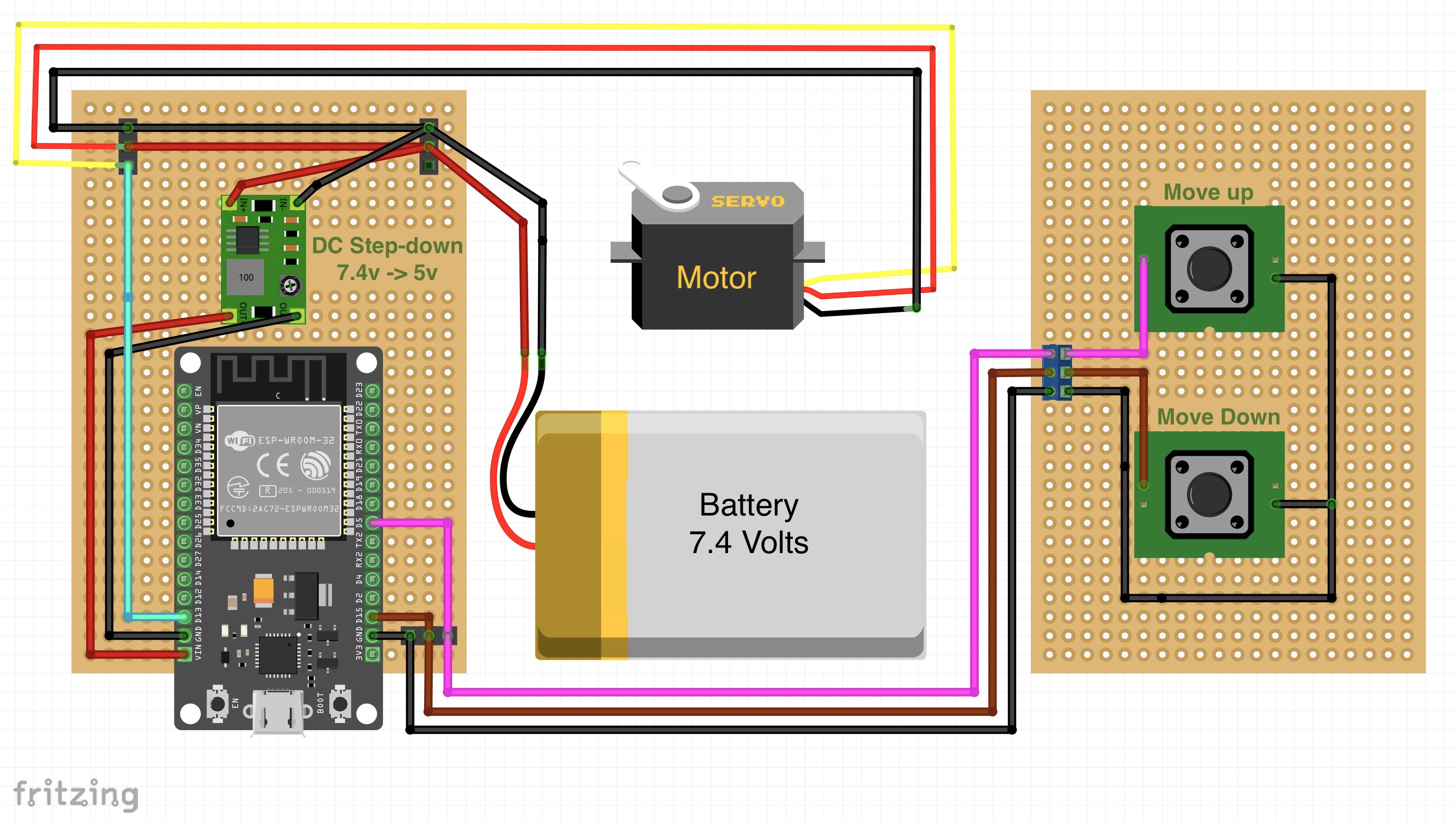
Diagram of the shade controller prototype circuit.
In the diagram on the right there’s the remote, with 2 buttons - up and down. Like we saw earlier in the basic circuit, each button is responsible to spin the motor in a different direction (i.e. clockwise/counter-clockwise). The motor receives the commands from the ESP32 using the cyan/yellow wire.
The circuit is powered by a single 7.4v battery. The motor can run with 5v, but it’ll run faster and provide more torque with a higher voltage. According to its spec, the motor’s safest maximum voltage is 7.4v, which is why I picked a 7.4v battery for the job. The motor is connected directly to the battery, but the ESP32 is more sensitive and could be damaged by voltage too high. To be on the safe side, I added a DC step-down convertor (a.k.a Buck Converter or BEC - Battery Eliminator Circuit) that will convert the battery’s 7.4v to a steady 5v that will power the ESP32.
The ESP32 chip itself is powered using 3.3v, but the dev-board it comes with has a built-in voltage regulator that can take a higher voltage and step it down to the needed 3.3v. That’s why it’s possible to power it via micro-USB, which provides 5v. When using an ESP32 dev-board, I can either connect a 3.3v power supply to the 3v3 pin, or I can connect 5v to the VIN pin which will first go through the built-in regulator. In the diagram, the DC step-down converter is connected to the battery on one side, where it receives 7.4v, and outputs 5v on the other side, which is connected to the VIN pin using the red wire.
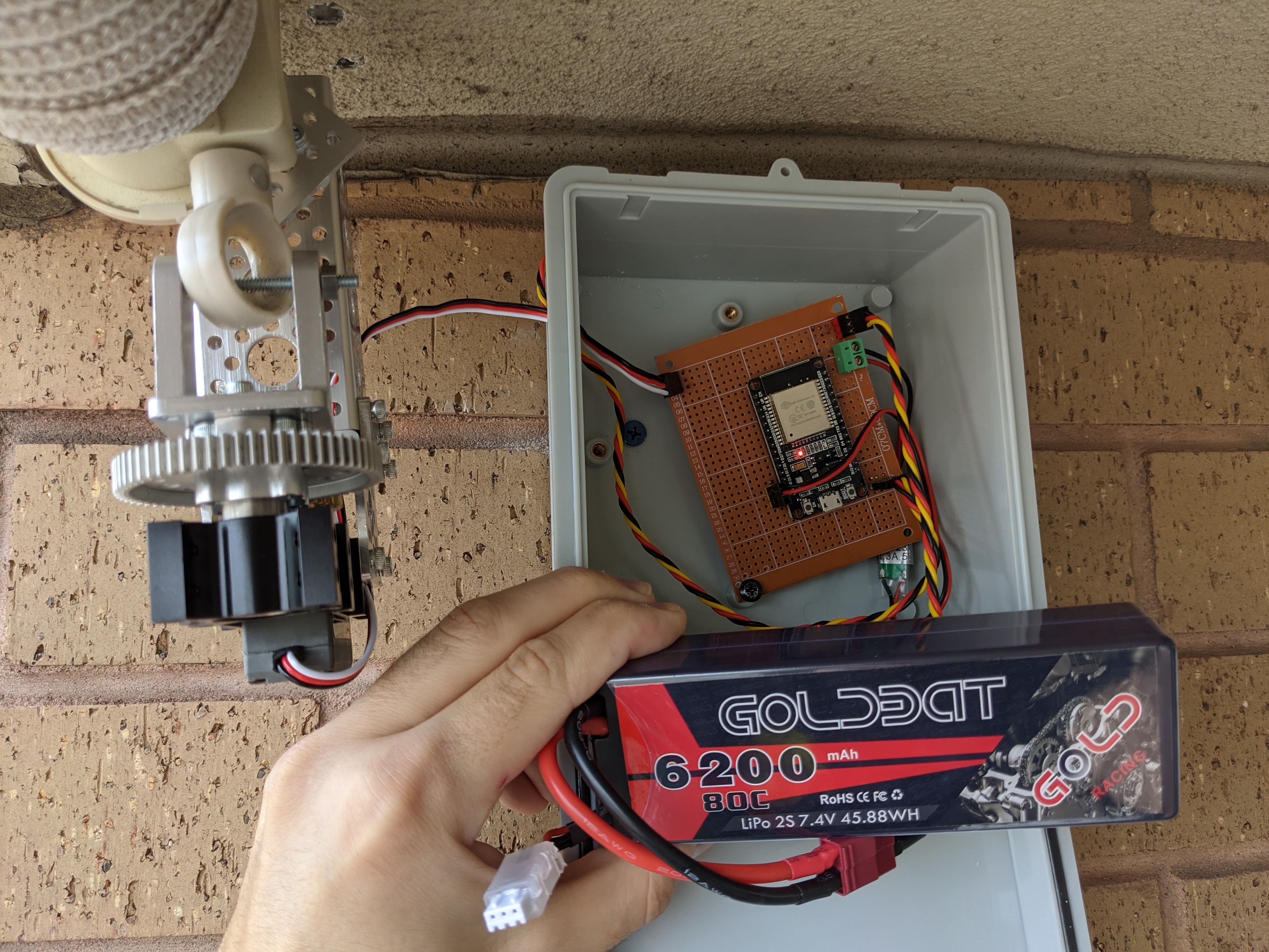
The prototype with the battery powering it.
After using the prototype for some time, I noticed a problem - the battery life isn’t great, a full battery lasted only 5 days.
I got a pretty strong battery, a 6200mAh LiPo 7.4v battery, which is intended for Remote Control race cars. The motor draws between 200mA-3000mA while running, which the battery can handle as it’s designed for operating strong race car motors, but the majority of time the circuit is on standby. While on standby, the ESP32 is powered on and waiting for input from one of the buttons, which consumes about 50mA. The battery’s capacity is 6200mAh, meaning it can power a 50mA device for 124 hours (6200 / 50 = 124), which is a little over 5 days. This aligns with what I saw in practice and explains why the battery doesn’t last that long.
I decided that the best solution is to simply ditch the battery. Why? I can’t see myself optimizing the battery consumption in a significant way. In addition, even if the battery will last a few weeks or a month, I still need to recharge it from time to time and risk having a dead battery when I need the shade. I don’t want to think about it, I want it to Just Work.
Connecting the circuit to a power adapter.
To support a power adapter, I added a barrel-jack port to my circuit and got a power adapter that supplies 7.5v. A pretty simple modification that means I don’t need to worry about sitting in the sun because I forgot to charge the battery in time.
That was the first modification I made to the shade controller’s circuit, but it was just the beginning. In the next section, I’ll go over a new feature for my shade controller that would require bigger changes, including communicating with an external chip.
Supporting Automatic Stops Using NFC
At this point of the project I got the minimal features for a fully working motorized shade, but I wanted to take this a step further. It takes a single button press to start lowering/raising the shade, but I still need to wait and press the button again in order to stop it.
In most cases, I want to fully lower the shade or fully open it, so it makes sense the controller should know when to stop instead of waiting for me to do it manually. In addition, the shade I have installed in my balcony is larger than the area it needs to cover, so I need to set clear boundaries and prevent lowering it too low or raising it higher than necessary. Otherwise, the motor or the shade’s roller could be damaged, or worse - my downstairs neighbor will come over to complain about the shade dangling above his head. By having a reliable way to know the shade’s position, I can program the shade controller to stop automatically when reaching a specific position.
There are several ways this can be accomplished. One way could be calibrating the controller with the time it takes to fully lower / raise the shade, then use this time to know how long the controller should spin the motor before stopping it. This method is simple to implement but also unreliable, since the duration of lowering/raising the shade could skew over time and require frequent calibrations (e.g. strong winds could pull the shade and create resistance to the motor, which slows it down). Another option is to stick 2 magnets on the shade itself, one at the top and the other at the bottom, then use a Hall effect sensor to detect these magnets and stop the motor from rolling the shade past these points. While this could work for simple use cases, it won’t prevent moving the shade past the boundaries the magnets created. For example, pressing “down” will lower the shade until the magnet is reached, but afterwards I can press “down” again to lower the shade further, past the lowest position allowed.
I decided to try an interesting approach - using NFC to read position markers on the shade. The problem with the magnets approach is the fact they aren’t distinguishable, so the shade controller can’t know which magnet is caught by the Hall effect sensor. Using an NFC reader, the shade controller can read NFC tags placed on the shade in different places and decide whether to stop or continue raising/lowering the shade. The NFC tags are distinguishable by their ID, but they also allow writing data in them, which can be used for storing in each NFC tag the position it represents (e.g. “100% open”, “50% open”).
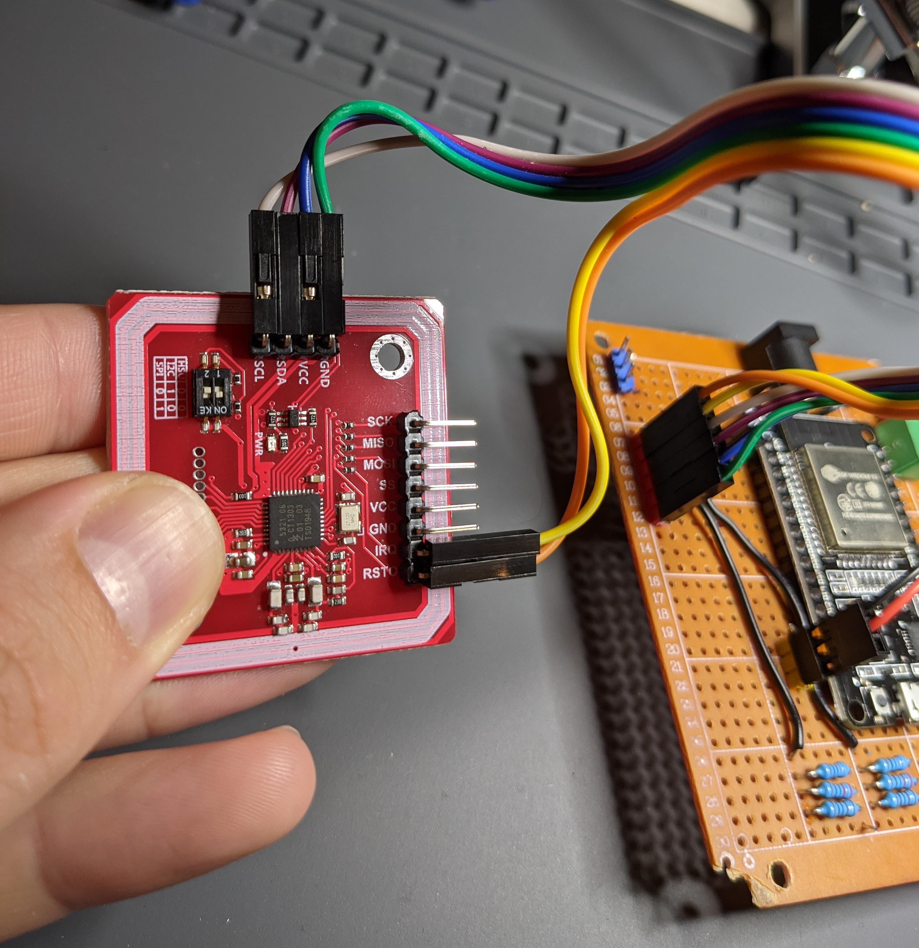
The PN532 is the most popular NFC/RFID chip. Pretty much all the mobile phones who support NFC use this chip, or other chips from the same company, to do things like wireless payments or sharing data between nearby devices. When I started tinkering with NFC I got the Adafruit PN532 breakout board, but I later got me a much smaller PN532 module, which works the same and will be easier to mount next to the shade controller.
The PN532 NFC Module.
There are several ways to connect peripherals to microcontrollers such as the ESP32 or Arduino. A peripheral can be a temperature sensor, LCD display or an external NFC module such as the PN532. Both Arduino and ESP32 support 3 common communication protocols - UART, SPI and I2C. Each protocol has its own benefits/drawbacks and picking which one to use really depends on the use case. SPI for example is much faster than I2C, which means it’s probably better for communicating with LCD displays or sensors that are sampled frequently, but with I2C we can connect a lot more external devices at once.
I decided to connect the PN532 NFC module using I2C ( = inter-integrated circuit), because it’s a simpler connection but also for a reason I’ll cover a little later. Here’s a diagram showing how everything is connected:
Diagram of the main circuit connected to the PN532 NFC module.
There are 4 main wires necessary to connect the PN532 to the ESP32. First the power pins, VCC and GND, are connected using the blue and green wires to the 3v3 and GND pins on the ESP32. These will give the PN532 the 3v it needs to be powered. Next are the communication pins - for the I2C protocol we need to connect the SCL (clock line) and SDA (data line) pins to the equivalent pins on the microcontroller, which for the ESP32 are the D22 and D24 pins. In the diagram, these are represented by the white and purple wires. The orange wire is connected to the RESET pin, it’s optional and used to reset the device if needed. The yellow wire is connected to the IRQ pin, which will be discussed a bit later.
There’s another connection we need to make for the I2C interface to work properly - the SCL and SDA pins also need to be connected to the power line (i.e. the 3v3 pin). This is necessary due to the open drain design of I2C - during data transfer the SDA/SCL lines are pulled low, which is a problem if other devices also try to communicate. To make I2C work, we need to keep these lines high by allowing power from the 3v3 pin to come through. But, the power can be too strong, which is why I had to connect 1.5kΩ resistors per line (I didn’t have a single 1.5kΩ resistor, so I just connected 3 that totaled in 1.5kΩ). There’s more discussion on this subject here.
Writing the code to interact with the NFC chip was pretty straightforward using the Adafruit PN532 library - there’s an API method that starts listening for cards/tags, waits for a card to come close to the reader and reads its data when that happens. It looks simple, but there’s one major problem for my use-case - the command that starts listening for NFC cards is a blocking call. This means my microcontroller, the ESP32, is essentially stuck waiting for NFC tags and can’t respond to other inputs, such as button presses. Here’s how this looks in the code:
// Pin definitions#define PN532_IRQ (2)
#define PN532_RESET (4)
// ...voidloop(){// ...// The DOWN button is pressed if(btnDownCurr==LOW&&btnDownPrev==HIGH){if(raisingShade||loweringShade){stopShade();}else{lowerShade();// Wait for the NFC module to detect a card or a tag and read it.// This is a BLOCKING call.success=nfc.readPassiveTargetID(PN532_MIFARE_ISO14443A,uid,&uidLength);if(success){// Get card ID and check if we need to stop the motor}}}// ...}
For example, say I press the “down” button to lower the shade all the way down. While the motor is running, the ESP32 will activate the NFC module and wait for the NFC tag that signals the end of the shade. But, during this time the buttons aren’t responsive, which means there’s nothing I can do to stop lowering the shade before it reaches the end.
I needed to find a way to make the microcontroller wait for NFC tags and still be responsive to new commands, but there were no API methods to help with that. I saw others use a second ESP32 with the sole purpose of waiting for NFC cards, then communicating that to the first ESP32. That’s probably an overkill.. I decided to dig a little deeper into the NFC module’s spec sheet and find a better solution.
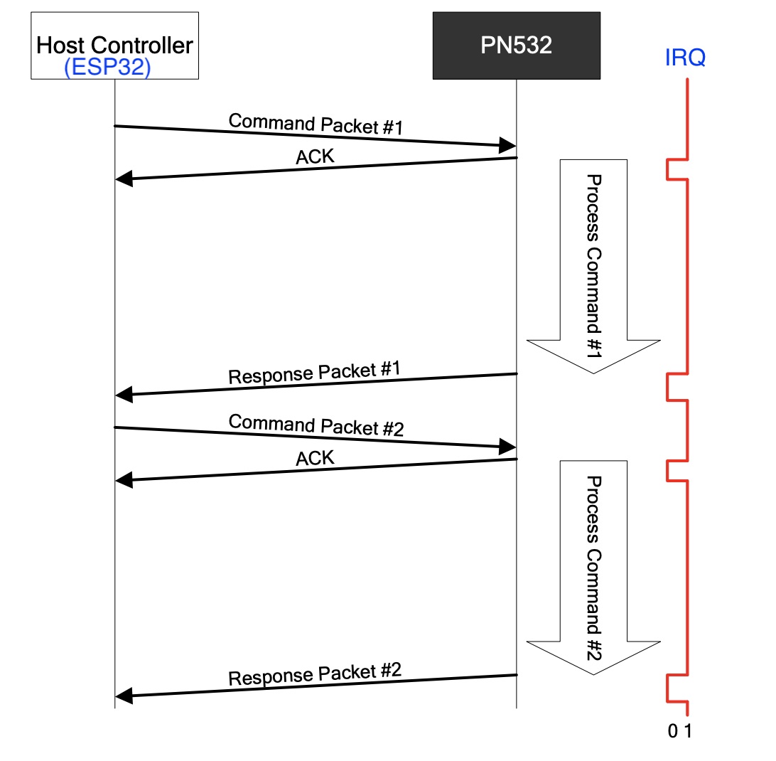
According to the PN532 user manual, we can use the chip’s IRQ pin in order to be notified asynchronously when a card is detected. The IRQ line is an optional connection we can make between the host controller (i.e. The ESP32) and the PN532 NFC module. When everything is connected and working, the PN532 will continuously send high voltage in the IRQ line, which essentially means we’ll get a binary 1 value whenever we read from that pin. When the PN532 has some response it wants to notify the host controller about (e.g. new NFC card/tag was detected) - it momentarily drives this line low ( = sends a binary 0 instead of 1 for a short amount of time).
Sequence diagram showing the changes in the IRQ line when messages are sent and received between the ESP32 and PN532.
I connected the IRQ pin using the yellow wire in the diagram above, then updated my code to keep track of its value. The ability to use the IRQ line is the reason I chose the I2C protocol over SPI and UART - the Adafruit PN532 library supports the IRQ pin only when connected using I2C. However, this library didn’t include a non-blocking API to put the NFC module in a card detection state. So.. I just added new API methods myself! Here’s the updated code:
// API for the NFC module (PN532 chip)Adafruit_PN532nfc(PN532_IRQ,PN532_RESET);// Supported NFC tags for each shade position (0%, 100% etc.)constuint32_tCARDID_100_PERCENT=3952824665;constuint32_tCARDID_0_PERCENT=913822226;// ..voidsetup(){pinMode(PN532_IRQ,INPUT_PULLUP);// ...}// Main function that loops as long as the controller is powered onvoidloop(){irqCurr=digitalRead(PN532_IRQ);// ...// The DOWN button is pressedif(btnDownCurr==LOW&&btnDownPrev==HIGH){if(raisingShade||loweringShade){stopShade();}else{lowerShade();// Puts the NFC module on a listening mode, a NON-BLOCKING callnfc.startPassiveTargetIDDetection(PN532_MIFARE_ISO14443A);listeningToNFC=true;}}// If the NFC module is currently listening and we’re notified via the// IRQ line that a card was detectedif(listeningToNFC&&irqCurr==LOW&&irqPrev==HIGH){// Read the detected NFC tag's infosuccess=nfc.readDetectedPassiveTargetID(uid,&uidLength);if(success){// If the tag is valid, we'll read its IDuint32_tcardId=getCardId(uid,uidLength);if(cardId==CARDID_0_PERCENT){if(loweringShade){// Found the "0% open" position tag while lowering the shade, // we can stop because the shade is now fully closedstopShade();listeningToNFC=false;}elseif(raisingShade){// Ignoring.. }}elseif(cardId==CARDID_100_PERCENT){// Similar implementation as above.// Stop raising the shade when the CARDID_100_PERCENT tag is detected, // since the shade is now fully open.}}// If we didn't stop the motor and still need to listen to NFC tagsif(listeningToNFC){delay(500);// Puts the NFC module on a listening mode againnfc.startPassiveTargetIDDetection(PN532_MIFARE_ISO14443A);}}// ...}
Using the new API, I put the NFC module in a detection mode without blocking. During this time, if the IRQ value changes from HIGH to LOW - we know a card/tag was detected and it’s time to try reading it. Each NFC tag represents a shade position (e.g. 0% opened), which will help determine whether the motor needs to be stopped. We can attach more NFC tags to the shade and support more “shade presets”, like 50% or 25% open.
The new API methods I added were merged into the PN532 library, now everyone can use them! There’s more info in the pull-request I made on Github.
With these changes, the up/down buttons are always responsive and the motor can be stopped either by pressing any of the buttons or when the NFC module is reading the appropriate NFC tag. The next video demonstrate this in my development environment, note how I use a different NFC tag to stop each spin direction:
Testing the new NFC-based auto-stop mechanism
By the way, I could’ve used another Arduino feature called Interrupts to listen and react to changes in the IRQ line. While interrupts might seem as a more elegant implementation, they also cause disruptions to the execution flow which made the shade controller unreliable in some situations. With more effort, I might be able to get interrupts to work for me, but for now I chose the approach above for its flexibility and consistency.
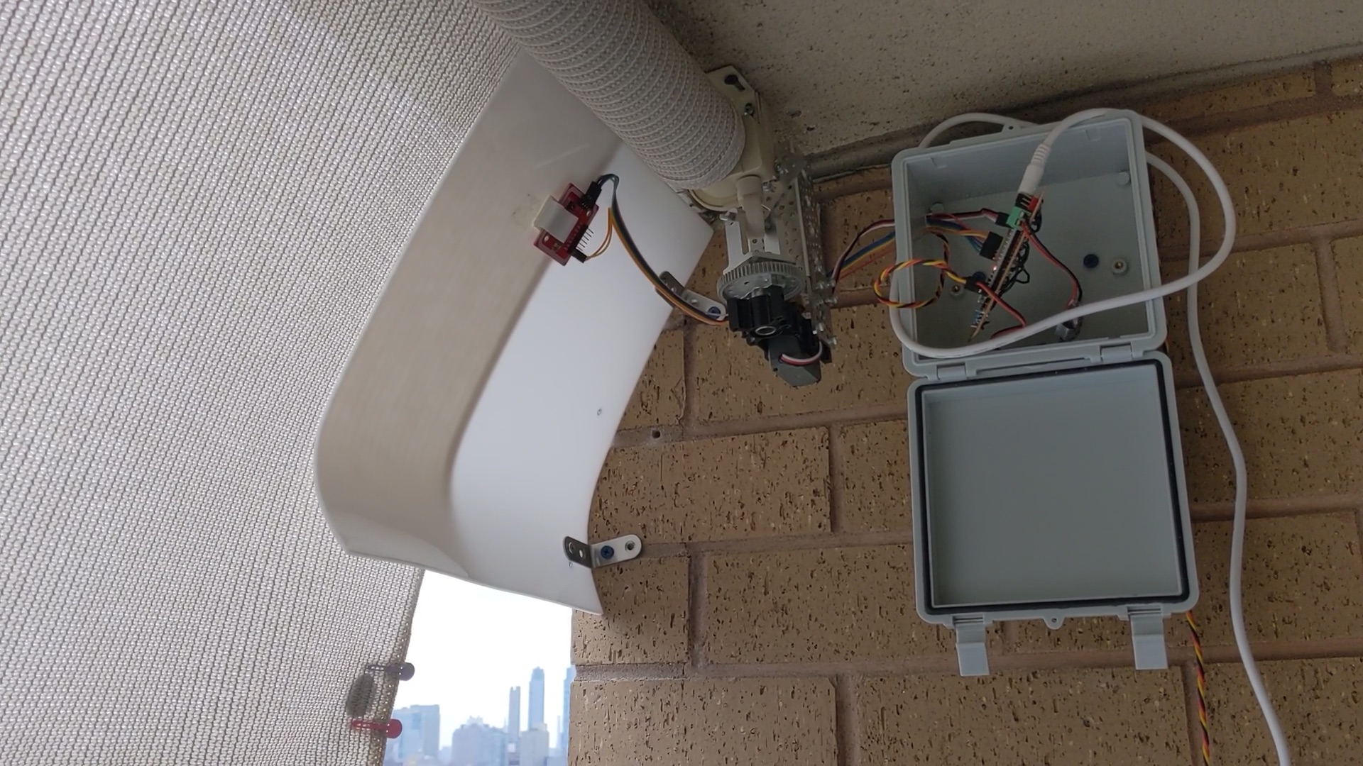
To test this NFC-based positioning system on my balcony shade, I need to put it close to the shade. For that, I got a plastic sheet from Amazon to hold the NFC module on one side and supports the shade on the other. The shade rests on this plastic sheet as it moves up or down, allowing the NFC module to read the NFC tag that’s on the shade. In my first test, I attached an NFC tag on the shade using 2 of my daughter’s hair clips (I couldn’t find a stapler ¯\_(ツ)_/¯ ), and verified the shade controller stops the motor after detecting the NFC tag.
Testing the shade controller auto-stops when reaching the end.
The NFC module can read tags that are up to 2 inches away, which is more than enough for my setup, as long as the reader is aligned with the NFC tag attached to the shade.
Supporting automatic stops is a big step up for my shade controller. This new feature is making the shade controller more user friendly, robust and reliable. It’s also the foundation for the next major feature - voice command.
Hardware facelift
My shade controller is more automatic now, but how about making it look more professional? It’s a little too fragile (especially with children around), not weather resistant and looks kinda hacky. Before adding more software features, I decided to spend some time polishing the hardware side, making it more user friendly and sustainable.
As a first step, I created a switch box to replace the remote I created earlier.
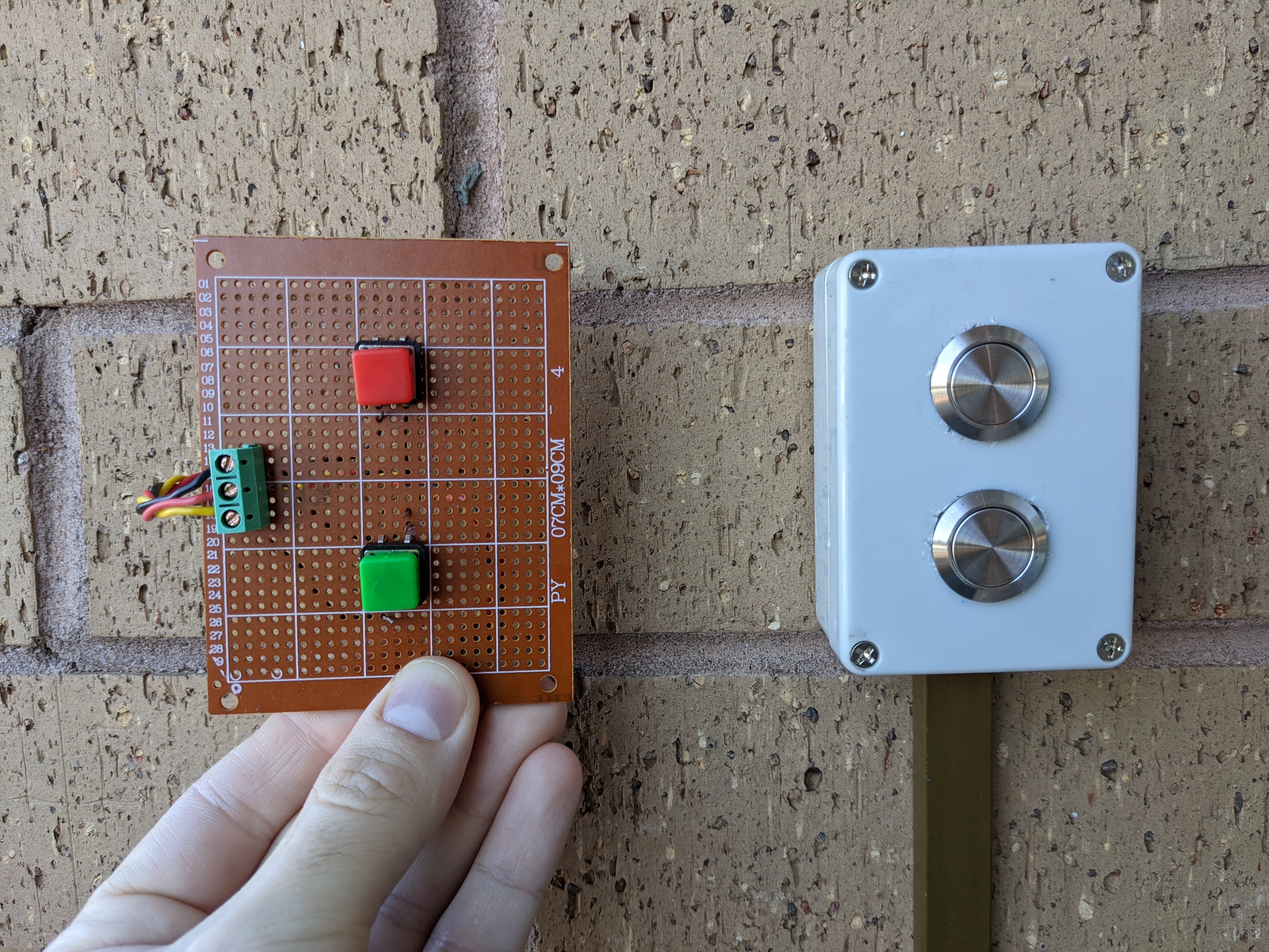
The old remote alongside the new waterproof switch box.
I drilled a couple of holes into a waterproof plastic box, where I installed the 2 waterproof buttons. I organized all the wires inside cable channels to protect them from the rain, and more importantly - my kids. Besides the robustness of the new switch box, it’s also a lot nicer than that hacky-looking remote.
The main circuit used to sit inside its own box next to the motor, but that was before I added the NFC module. For a cleaner look, I put both of them in the same box and mounted it on that plastic sheet the shade is resting on. The NFC module is still positioned close enough to read NFC tags from the shade.
While I was doing that, I figured I could reduce the footprint even further by trimming the plastic sheet, since I don’t really need it to be this big. I took a hacksaw and removed a significant chunk of it.
Before and after the changes to the main circuit housing.
Now I have the same shade controller, just better looking and with a much smaller footprint. This will be useful when I’ll need to explain all this to my wife
Now that looks a lot nicer!.
As one last improvement, I wanted to polish my circuit and create a PCB (Printed Circuit Board) to replace the perfboard I was using this far. Perfboards are a great way to quickly create and iterate on a prototype; they are less flexible than breadboards, but more sustainable and reliable. Now that I’m done with hardware changes, at least for the near future, a PCB will look a lot nicer and reduces the amount of loose wires that could be accidentally damaged.
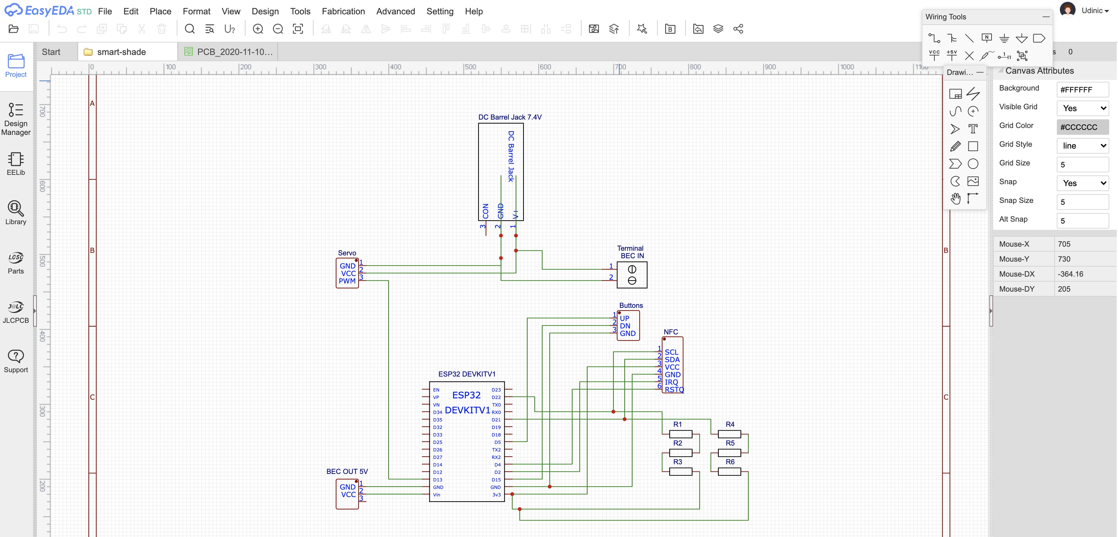
I never designed PCBs before, but it was simpler than I thought. I found EasyEDA, which is an online tool (and a Mac app) for designing PCBs and also ordering them directly from the tool. I started by creating the schematic design of my circuit:
The schematic design of the shade controller circuit.
The schematic is then used by EasyEDA to generate a PCB design. The design has all the components connected to each other, so I just moved components around to arrange them a little better, added labels and other small tweaks. Here’s what I came up with:
The PCB design in EasyEDA and the PCB I received.
The red and blue lines, in the PCB design, are the wires that connect the different components on the PCB and are generated based on the circuit’s schematic design. The reds are on the top layer of the PCB and the blues are on the bottom layer. This layer separation is necessary because the wires cannot cross each other and there isn’t always a way around to get the wire where it needs to go. Complex circuits might require moving components around in order to allow all the wires to be connected. There’s also an option to add images and text to the PCB, so I added a small logo and versioning information.
EasyEDA has the option to directly order the PCB from JLCPCB, a Chinese company that manufactures PCBs. I picked the color I wanted (there are 6 options!) and paid the $2 the PCBs cost (+ $16 shipping to the US), then waited about a week until they arrived (min. of 5 PCBs per order). After some quality time with my soldering iron, I got me a slick new shade controller circuit:
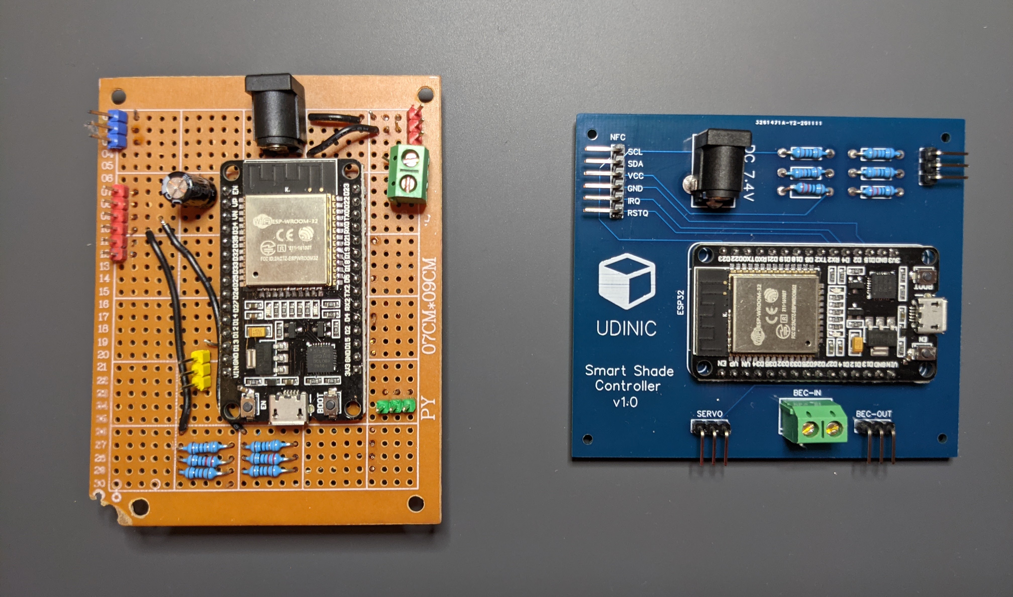
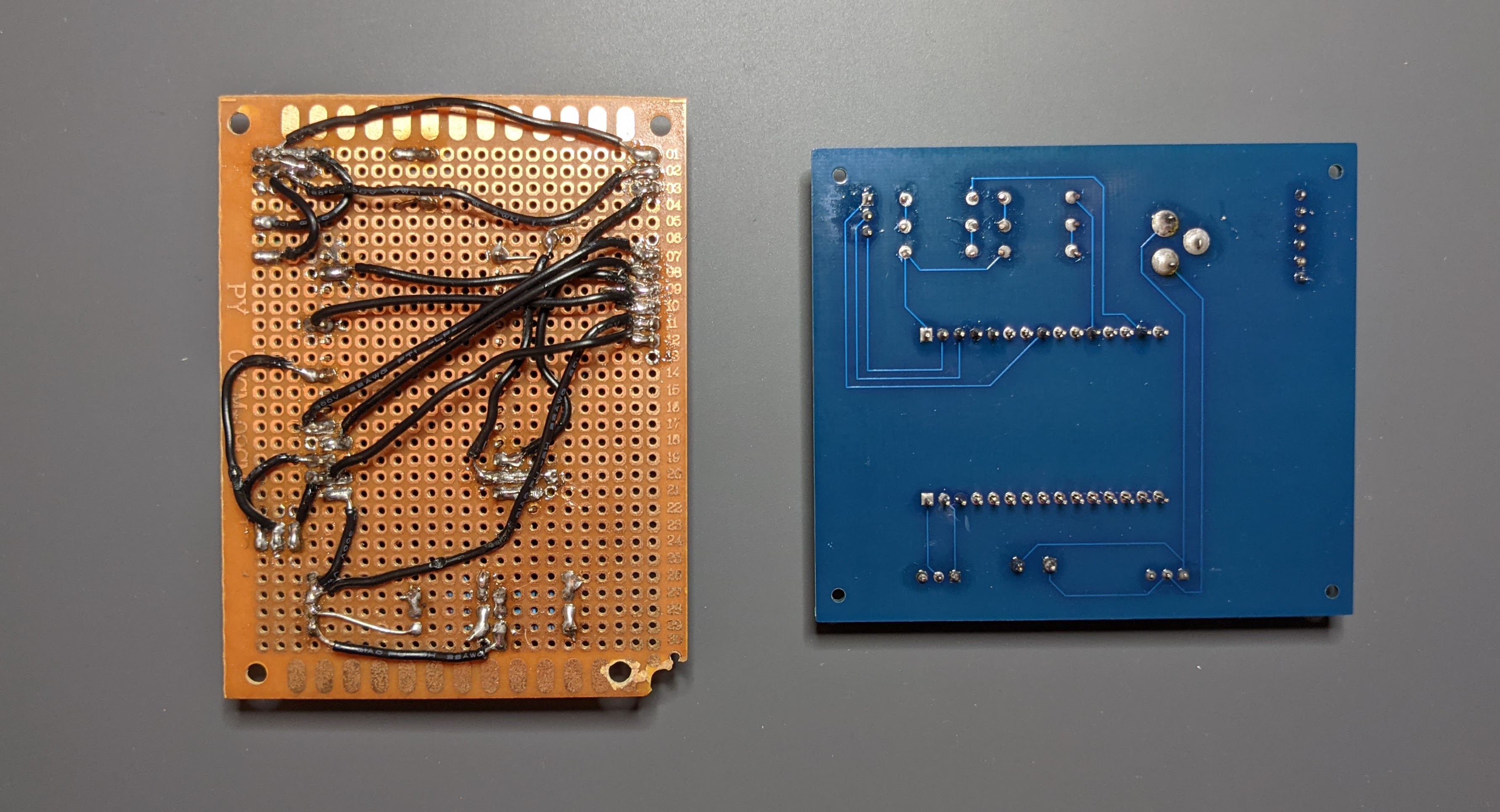
The old circuit compared to the PCB I designed.
Improving the look and feel of a product is not just a cosmetic change best saved for last, it can be an important step in the testing phase. With these improvements, I made the shade controller more accessible and user friendly. I feel more confident letting my kids use it now, which might expose usage problems I didn’t see before. Plus, it’s nice to clean up a bit before moving forward, it’s more fun to use a polished product and it helps seeing potential problems more clearly.
Supporting Voice Commands via Google Assistant
One of the reasons I switched very early on from an Arduino board to ESP32, is the WiFi support. This opens up new possibilities for my shade controller, the main one I was after is supporting Google Assistant and responding to voice commands. This is the change that will upgrade the shade controller to be a “smart shade controller” 😎.
There are a couple of ways I could use the WiFi support for controlling my circuit remotely. With a web server running on the ESP32, I can connect clients directly to it and communicate over HTTP requests/responses. The web server can be accessible on the internet or by a direct connection (example project that connects two ESP32s to each other without internet). While creating a web server on the ESP32 is a powerful feature, it has a few disadvantages such as a large overhead per message, speed and battery performance.
Another way to communicate with an ESP32 via WiFi is by using MQTT, a lightweight messaging protocol. MQTT is more performant and lightweight than HTTP, it also provides a simpler two-way communication mechanism between the ESP32 and its clients. For these reasons, MQTT is the preferred method for communicating with IoT devices. To use MQTT we first need an MQTT broker, which is a fancy name for an MQTT server. Any message sent to the broker needs to include a “topic”, then only clients subscribed to that topic will receive that message.
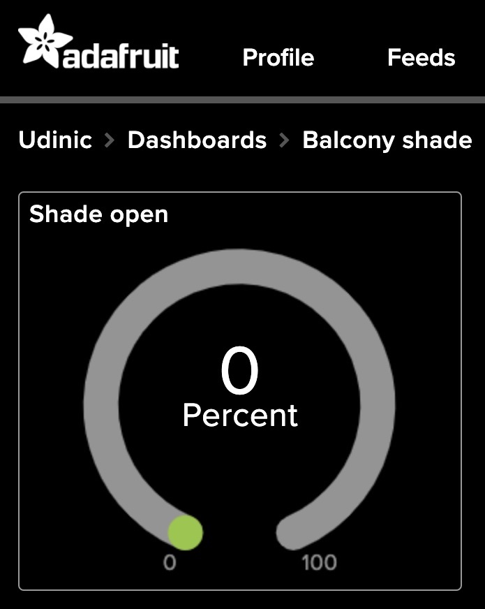
To set up MQTT for my shade controller, I can create an MQTT server in my local network (using Mosquitto) or use a cloud service such as Blynk or Adafruit IO. My needs are very simple and the free tier of a cloud service should suffice. I picked Adafruit IO, set up my account and added a new feed (i.e. MQTT Topic) for my project, called “shade-open”. In the web console, I can create a dashboard and see the latest value sent to that feed.
My shade controller dashboard on Adafruit IO.
To integrate and use Adafruit IO in the shade controller, I added their Arduino library into my project and made some changes:
#define IO_USERNAME "< AIO Username >"
#define IO_KEY "< AIO KEY >"
#define WIFI_SSID "< Wifi SSID >"
#define WIFI_PASS "< Wifi password >"
#include"AdafruitIO_WiFi.h"AdafruitIO_WiFiio(IO_USERNAME,IO_KEY,WIFI_SSID,WIFI_PASS);// Adafruit IO feed showing how much the shade should be open (either 0% or 100%)AdafruitIO_Feed*balconyShade=io.feed("shade-open");booleanconnectingInProgress=false;// …voidloop(){// Keep the connection alive, if already connected.// Times-out after 400ms to keep the microcontroller responsive.aio_status_tioStatus=io.run(400,true);// Connect to Adafruit IO, if connected then subscribe to the feedif(ioStatus<AIO_CONNECTED&&!connectingInProgress){connectingInProgress=true;io.connect();}elseif(ioStatus>=AIO_CONNECTED&&connectingInProgress){connectingInProgress=false;// Subscribe to the "shade-open" feedbalconyShade->onMessage(handleShadeLevelMessage);}// ...}// This function is called when a new message is sent to the “shade-open” feed.voidhandleShadeLevelMessage(AdafruitIO_Data*data){// Got a new message with the percent the shade should be open intpercentOpen=atoi(data->value());// If we're asked to open the shade to 100%, then raise it. Open to 0% means closing/lowering the shade.if(percentOpen==100){raiseShade();}elseif(percentOpen==0){lowerShade();}// ...}
The code connects to Adafruit IO cloud service and keeps the connection alive by calling the io.run() method in the main loop function. When a new message is posted to the “shade-open” feed, the callback function is called and sends the appropriate command to the motor.
I implemented the Adafruit IO integration a little bit differently than the examples they provide. In their examples, the microcontroller is blocked from doing anything until it’s connected to the cloud. I didn’t like the fact I won’t be able to use the physical buttons to control the shade while the controller is trying to connect to the cloud (do I really need to sit in the sun if my network is down or very slow?!). The code I wrote is more responsive and allows the controller to work offline, while still trying to regain connectivity. I tested the integration worked by sending MQTT messages from the Adafruit IO web console and verified they were received by the ESP32.
Now let’s move to the final part - controlling the shade from Google Assistant. This was probably the easiest part of this entire project. The shade controller can already take commands from the web using MQTT, so if we want Google Assistant to control it - we need to connect the two.
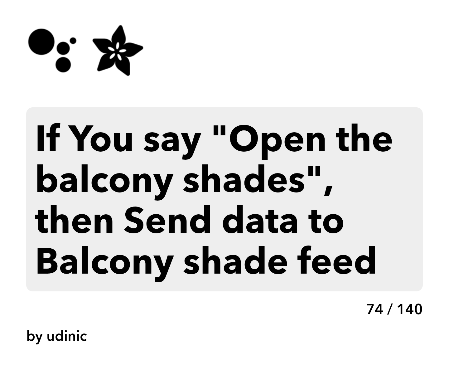
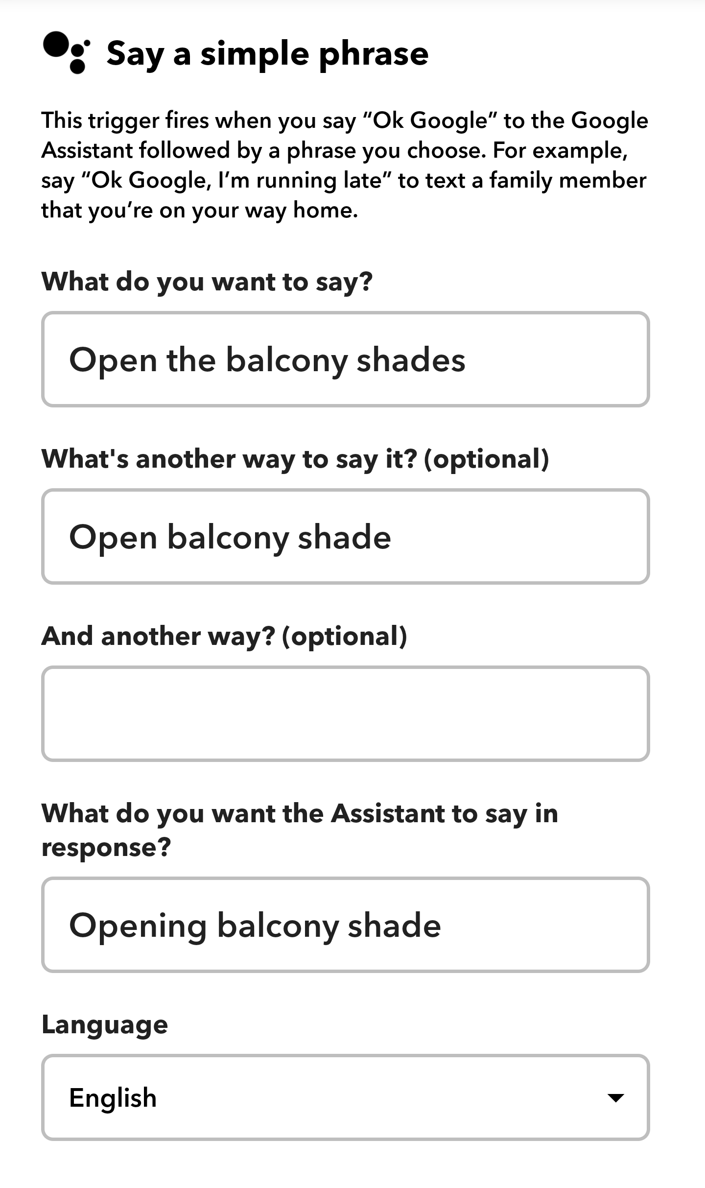
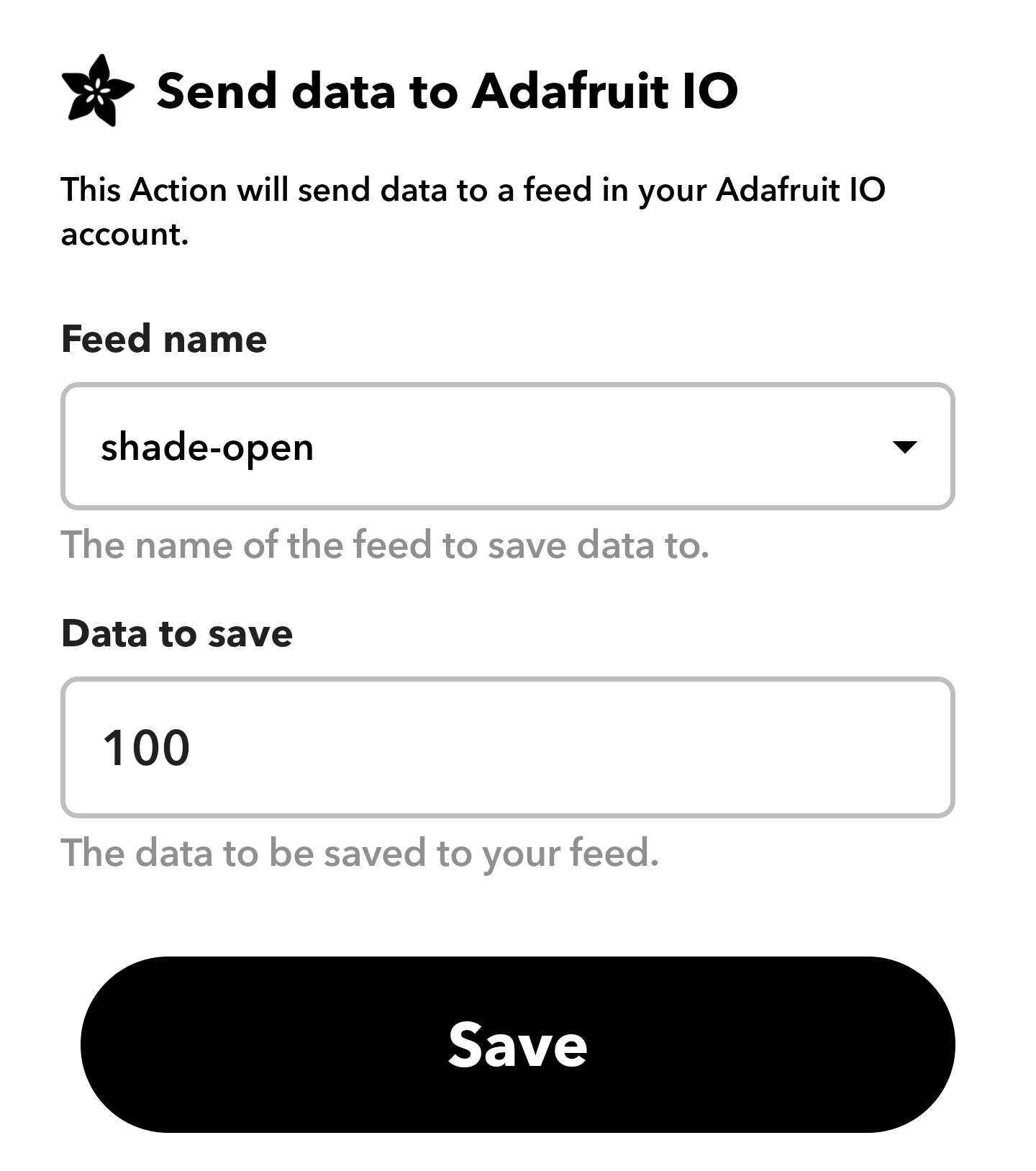
IFTTT (If-this-then-that) is a great tool for connecting different web services and products to each other. It supports integrations with Google Assistance and Adafruit IO, so all I needed to do is authenticate to both services and create rules (called “Applets”) to communicate between them. For my use case, I created an applet that reacts to a Google Assistant command to open or close the shade and sends data to a specific feed on my Adafruit IO account.
My IFTTT configuration for opening the shade from Google Assistant.
When I say “OK Google, Open the balcony shade”, Google Assistant will send the value “100” to the “shade-open” feed. The shade controller receives this message through Adafruit IO and raises the shade until it reaches the NFC tag that signals the shade is 100% open.
Here’s everything in action:
Testing voice command from Google Assistant.
Nice!
Final thoughts and tips
I spent weeks working on this project, I love how it turned out and what I gained from it. Operating my balcony shade is more convenient for sure, but that’s not even the most useful outcome of this project. For years, I’ve used software to improve different aspects of my life, but now I’ve gained the experience and confidence to build custom electrical products and unlocked a new type of solutions I can improve my life with. The potential is huge and I’m excited to see what I will do with it next.
I learned a lot of new things in this project, not all about electronics, and I think the best way to learn is to simply get your hands dirty and dig deeper as problems arise. I figured it’s worth mentioning a few quick tips from my experience working on this project, some I learned the hard way:
While I knew I wanted to add NFC support from the beginning, I went with an iterative approach - started with a simple circuit and made changes in steps. This might take a bit longer than completing the vision in one go, but it helps seeing and fixing problems early, before they become bigger or harder to pinpoint. The battery life problem is a good example for something I didn’t put too much thought into, but I was able to fix it before getting into the more complex NFC issues that came later.
I also recommend having a simple way to use the circuit in a development environment. After I mounted the motor and the switch box, I was still able to take the main circuit to my desk and debug problems using a simpler motor and remote. I also added a flag in the code for disabling the NFC, so I won’t have to connect an NFC module in my development environment unless I need to. This was really convenient and greatly improved my development process.
Breadboards can be unreliable, take that into account when testing your circuits. I spent hours on a problem with the NFC module, which turned out to be a result of jumper cables that got momentarily disconnected and caused weird state issues. If the circuit is not expected to change much, consider doing it on a perfboard.
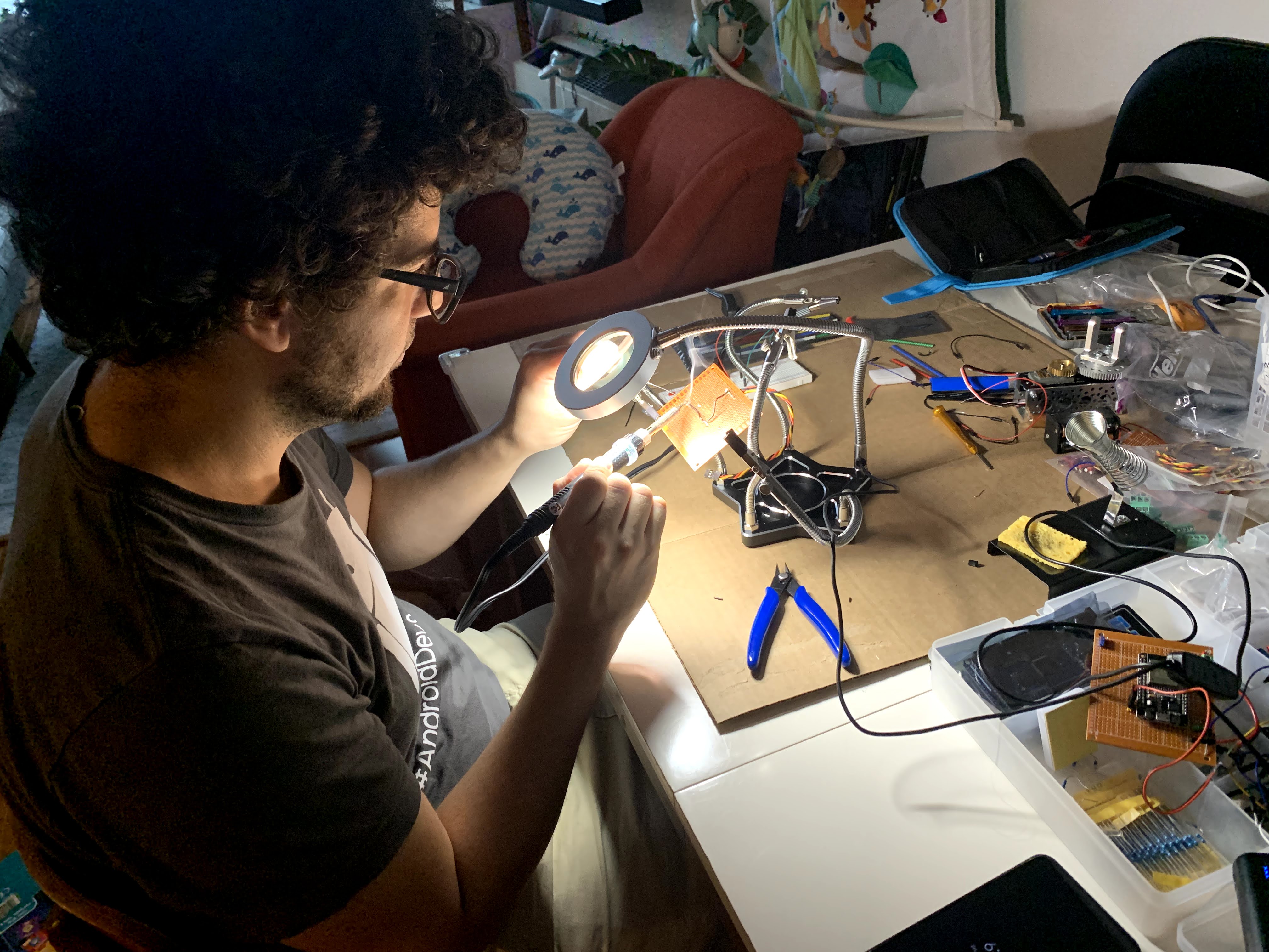
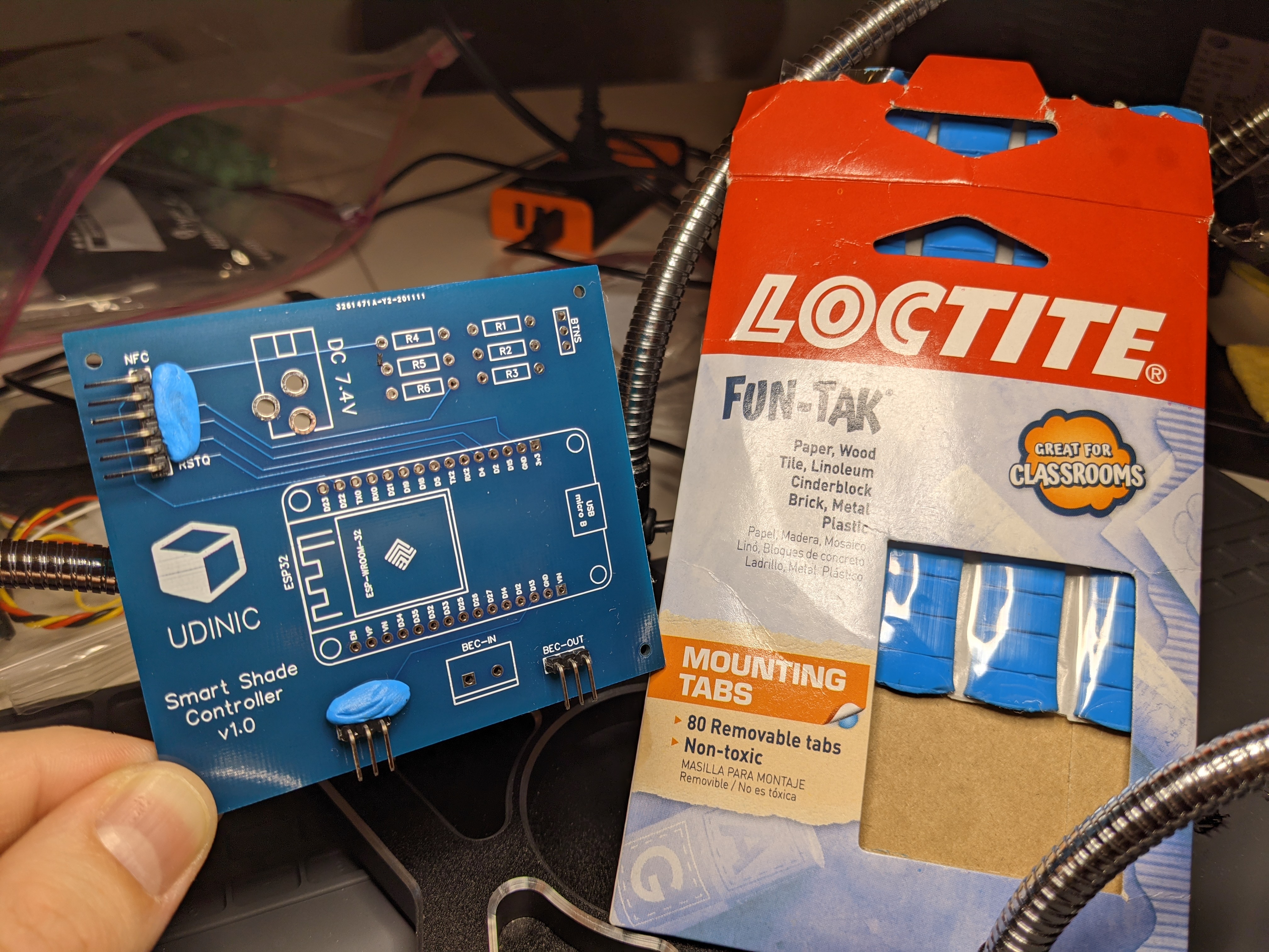
Soldering is an important skill and having the right tools can make a big difference. My circuits looked a lot more professional and less frustrating to make after I got me a helping hand - a soldering tool with arms for holding the circuit and other components while soldering. It also includes a strong light and magnifying glass.
One more soldering tip - some components are just hard to solder straight (I’m looking at you headers!). I learned I can use sticky mounting tabs to steadily position the components while soldering them. Really useful and made my circuits look more professional.
Soldering headers with mounting tabs.
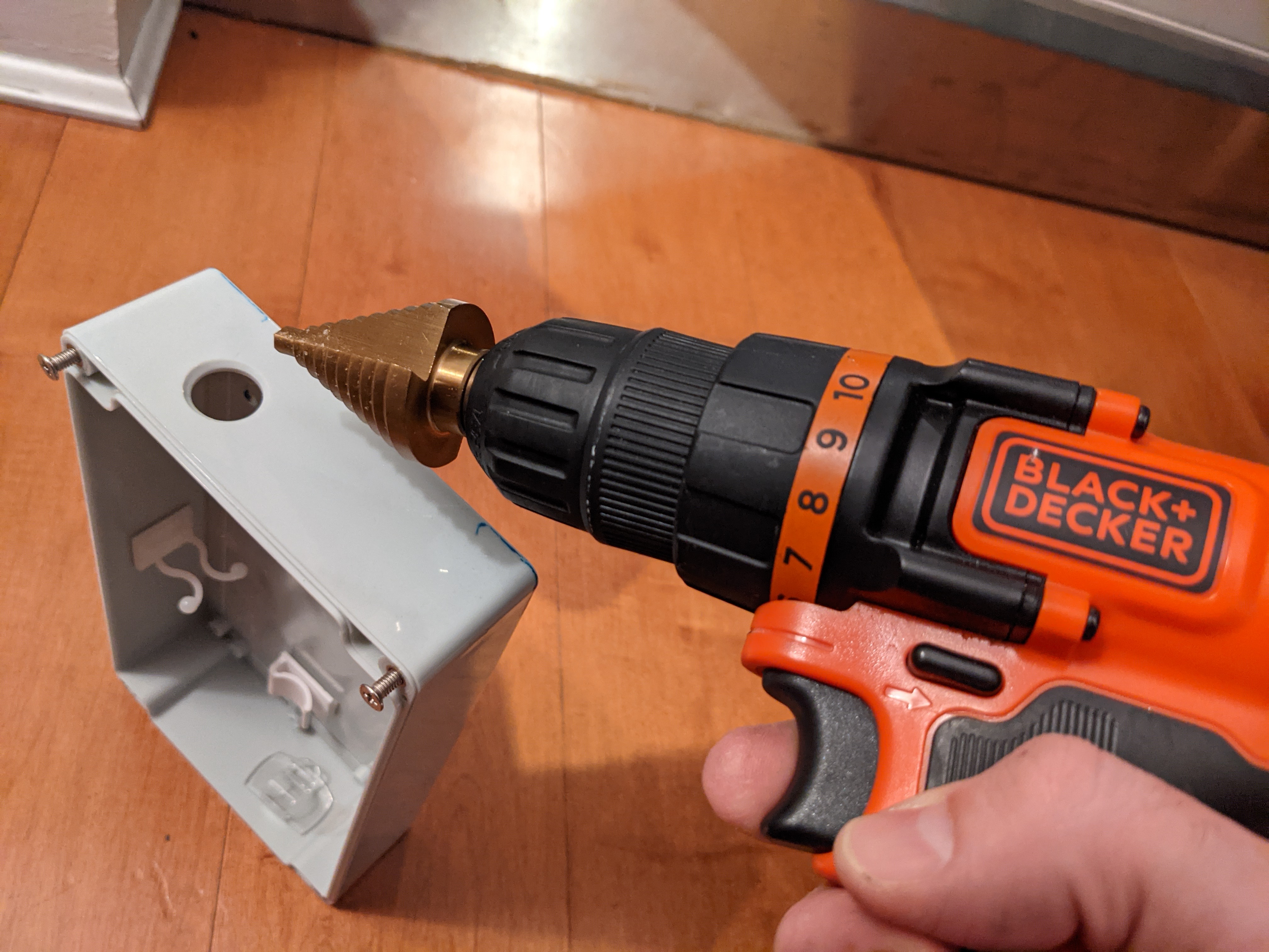
There was a lot of drilling in this project, and I learned a lot about types of surfaces and drills, but I think the highlight is getting to know the Step Drill for drilling perfect round holes in plastic boxes. I found out about this awesome drill bit after spending way too much time drilling holes in the switch box, for inserting the 2 up/down buttons. The Step drill can make the same holes in seconds, and perfectly round too. I think it’s a must for projects like this.
The Step drill bit and the clean hole I made with it.
That’s all! The source code and designs are available in the Resources section below, in addition to the list of components I used and other useful resources for this and similar projects.
Resources
The source files are available on Github, including the Fritzing diagrams, PCB schematic and Gerber files.
ServoCity - Where I bought the motor and a lot of other structural components that helped me mount the motor. Great site to look for interesting parts for different types of projects.
Adafruit - I got many of my components from Adafruit, they open-sourced great Arduino libraries and operate helpful forums. A must have for any hobbyist.
SparkFun - I liked their “where do I start” tutorials, which are a great refresher for the basics. SparkFun also makes and sells components, much like Adafruit.
UPDATE (09/2020): While I discontinued working on Grabag, this might still worth the read as the idea still lives on. To this day, I keep seeing this type of product being requested by people.
About a year ago, I cut the cords and canceled my cable subscription. I watch a lot of TV shows, but I stream everything anyway, and avoiding all the commercial breaks is a bliss.
But there was one thing I found hard to do after that - finding something random to watch.
I often like to watch an episode of something while eating dinner, or put in the background while I’m working on my computer. When I had cable, I would just put on a channel that plays South Park, Family Guy or some other light TV show episode. But without cable, I’d find myself open each streaming app and browse the episodes for the shows I like. In many occasions, I didn’t even care what should I watch, but the process still took me a few minutes each time (see The Paradox of Choice). That gave me the idea for an app that liberates me from making that decision over and over again, and that’s how Grabag was born.
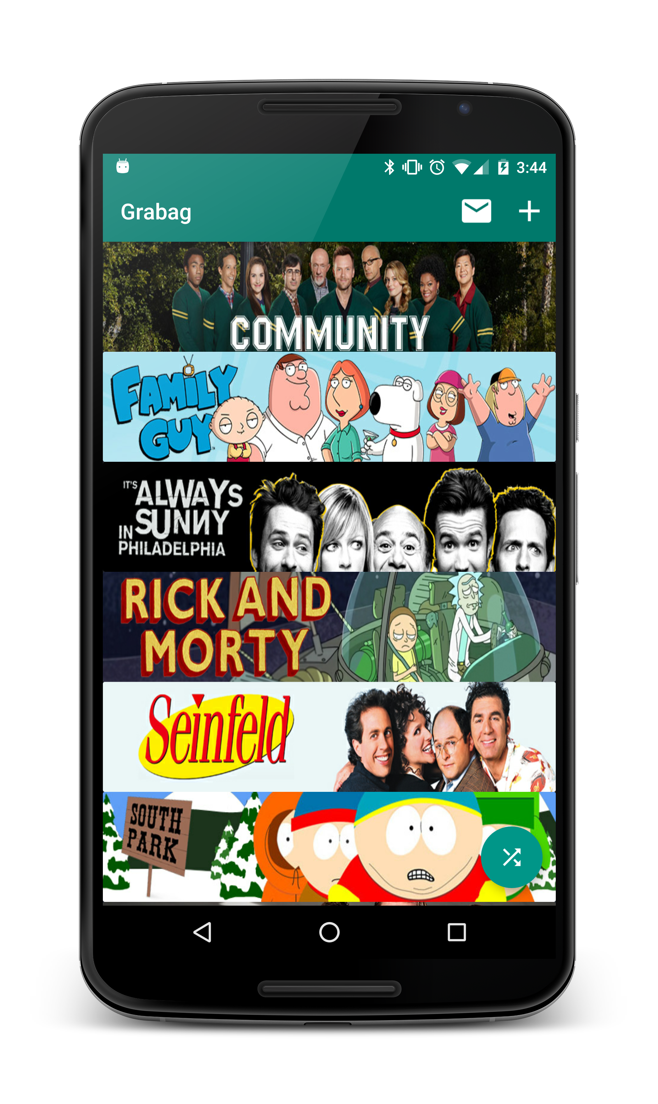
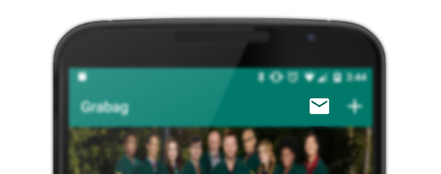
Grabag (Grab Bag) is very simple - pick the shows you like, and the app will randomly select an episode for you, along with a short description and a direct link to open it on an app that streams it (e.g. Hulu, HBO Go, Google Play). Here’s the main screen, where all the selected shows are listed:
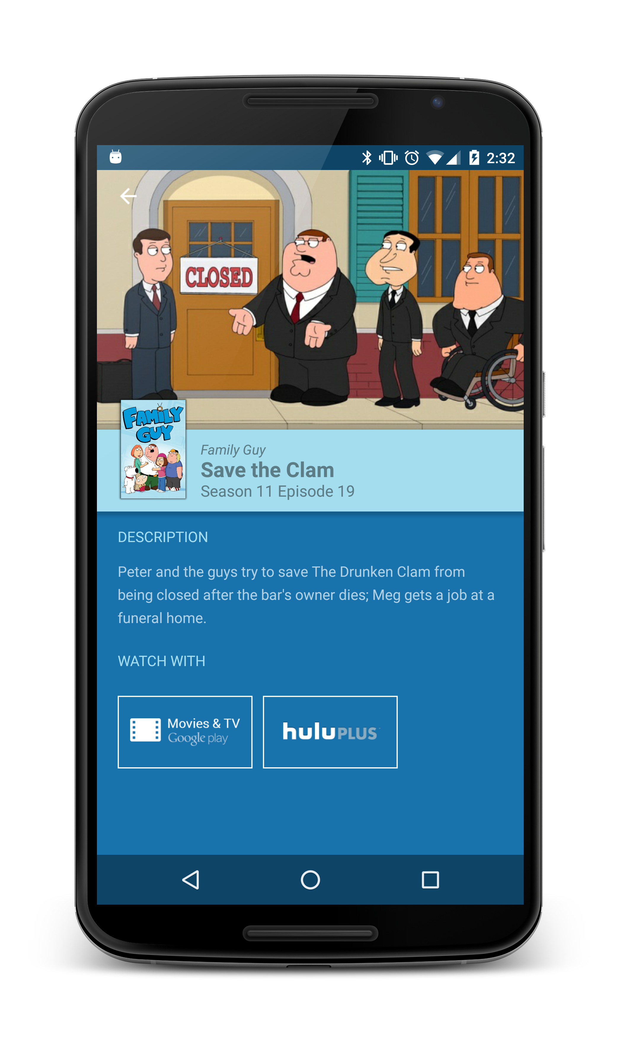
Clicking on each banner will pick a random episode for that show, and picking a random episode from all the shows is done using the bottom-right “random” button. Here’s an example for an episode:
Don’t like that one? No worries, just scroll right and get more.
To watch it, click on the streaming service button. That’s a direct link to play the episode on that app. You can later cast it to your TV, if you’d like.
There’s no sign-in requirement and the app is free.
Beta testing
I’ve been working on this app for a while now, and I’ve used it myself many times. I decided to make a beta release, getting users’ feedback, and later release it to the public. If you’re interested in joining the beta, just use this link to become a tester and download the app:
The app currently supports only “Hulu” and “Google Play Movies”, but other streaming services will be added real soon.
I hope this app will make your TV shows watching experience much simpler and relaxed, as it did for me. If you have an idea how to make it even better - don’t hesitate to contact me.
A few weeks ago, I gave a talk about Android Performance Optimization, at Droidcon NYC.
I invested a lot of time in this presentation, since I wanted to show real examples for performance issues, and how to identify them with the available tools. I had to cut down about a half of my slides because I didn’t have enough time to show everything. In this post, I’ll summarize everything I was talking about, and show examples I didn’t have time to go over.
The talk was recorded and you can watch it here:
The slides are also available:
Now, Let’s go over some of the important things I was talking about, hopefully I can give a deeper explanation for everything, starting with the basic rules I follow when I work on optimizations:
After several years of using Wordpress.com for my blog - I decided I need a change.
I wanted to move to something different for a while, but kept postponing it because that would require some time and effort to do. In this post, I’ll summarize my transition experience and elaborate on problems I had and how I solved them. Hopefully, this information will help others with similar ambitions.
Properly importing an AOSP repository into your source control
Use better ways to build modules and deploy to the device
Writing scripts for faster development process
I’ll use Git and Bash commands that you may not know, but can definitely search and learn as we go. You can also use this simple Bash scripting tutorial to get started.
On the previous post, we got the AOSP code into our environment and learned how that process works. The _repo _tool and the Manifest project goes hand-in-hand, managing the 200+ git repositories, all part of the AOSP.
Now that we have all the code locally, we need to get all those lines of code into a nice package we can eventually install on a device. The nice guys in Google brought us some nice utilities to help with that. To initialize your environment with those new functions and environment variables, you need to run the command:
$ source <working dir>/build/envsetup.sh
Note: I’m using Mac OS with “oh-my-zsh” and “zsh” as my default shell. When running this command from a shell other than “bash”, you’ll get a warning that only bash is supported. From my experience, I can tell that I never ran into a problem. If you know otherwise - let me know, otherwise - I highly recommend this configuration regardless of AOSP work.
6 months ago, I moved to New York, the first city I lived in outside of Israel.
With a new job at a new place, I decided to also try a new laptop running a new platform - Mac OS. I always used Windows before that. I have used Linux as a VM and on servers I worked on, but as a primary OS - I sticked with Windows (with no particular reason). After many recommendations, I decided to give Mac its big break. As one big advantage of Mac over Windows - I could build my own Android ROM (Android operation system software, running on a device), which i’ve wanted to try and do for a long time.
Last week, Romain Guy posted about Optimizing hardware layers. He explained how hardware layers are a great way to boost the performance of your animations, but can also degrade it.
When your view is backed by a hardware layer, that layer will get updated every time the view itself will update, and after that the layer will be drawn to the screen. Meaning, if your view is altered during an animation – more work is done per frame and you’ll get a drop in your frame-rate. That’s why it’s not wise to change your animated view while it’s backed by a HW layer.
On his post, Romain suggested an easy way to spot such problems, using the “Show hardware layers updates” under the Developer Options. Every time a HW layer is updated – it’ll be highlighted in green.
On my last post on the subject, Write your own Android Authenticator, we embarked on a journey to the unfamiliar part of authentication on Android. I received many positive responses about it from you all, and it seems I really helped a lot of people to get to know this feature well.
Since then, I had a lot of stuff going on in my life (getting married is one of them) which delayed the release of this obvious sequel. On this post, our journey continues to another not-well-documented area, which goes hand-in-hand with our own authenticator. It’s no other than the notorious SyncAdapter. I’ll show you how to make your app more efficient and robust when it comes to data synchronization, by using sync adapters. The web doesn’t have all the information I’d hope to find about it. I felt like I need to give this feature another one of my in-depth researches, see what this feature is all about, how it works, how to write one, and finally – report back.
In the screenshot: That’s how a sync adapter looks on the account screen, under the device’s Settings screen.
First, I’ll explain the benefits of the sync adapter. Then, how it works and after that how to build and monitor it. Finally, I’ll introduce the sample app I wrote, demonstrating how the sync adapter works, and also allowing you to play with its settings to learn from experience.